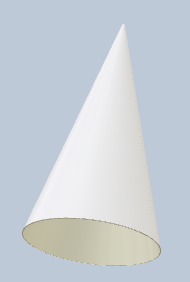
A surface folded into a cone
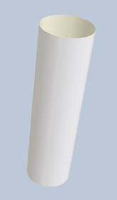
A surface folded into cylinder
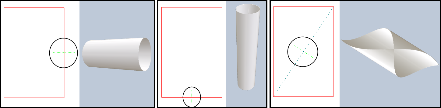
You can bend a surface and produce a conic or cylindrical shape.
A surface folded into a cone
A surface folded into cylinder
You achieve a cone or cylinder by setting a leading object in the 2D area. This is the object that EngView will use to perform the bending. If the object is an arc, the bending produces cone; if the object is a straight line, a cylinder. The procedure that follows guides you through the process of defining a conical / cylindrical object, and then performing the actual folding of a surface into a cone or cylinder.
To bend a surface into a cone
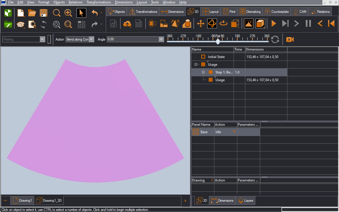
In the example that follows, we will bend the following structure into a cone.
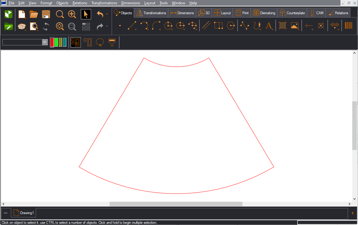
The procedure starts in the 2D area, where we create a 3D guideline object that EngView will use to perform conic bending in the 3D area.
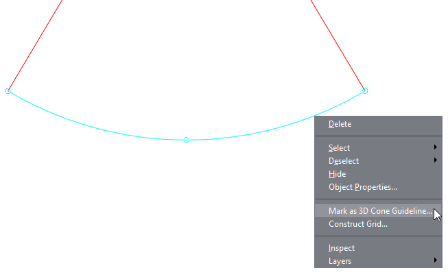
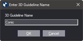
The Enter 3D Guideline Name dialog box appears.
The Cone 3D Guideline object was created with the name Conic. You see it in the Layers & Objects tab and in the 2D area.
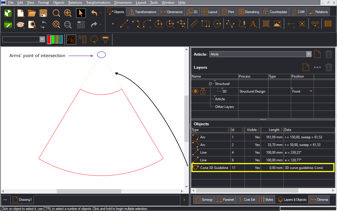
CAUTION: When adding a guideline, pay attention to the point (in lilac) where the guideline's arms (the green dashed lines in the image above) intersect. Make sure you position this point higher than the panel.
After creating the guideline object, we move to the 3D area, where we perform the bending.
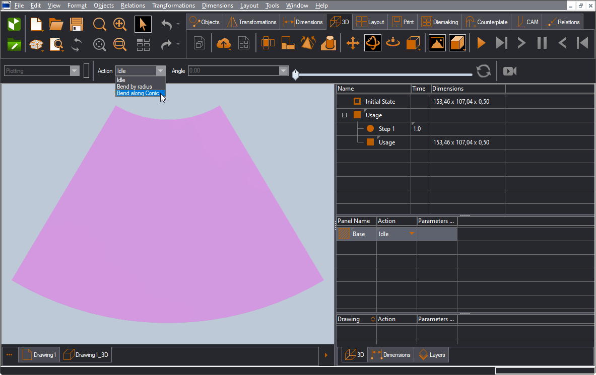
The plane is now ready for bending.
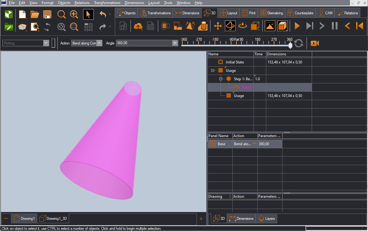
To bend the panel to a full cone, drag to 360 degrees. This means the bending will be along a 360-degree sweep:
To bend the panel to a partial cone, set a smaller sweep:
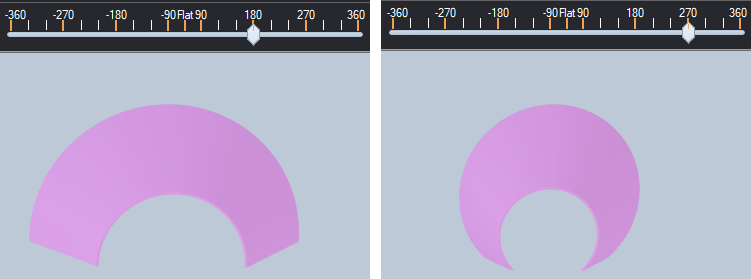
NOTE: The different sweeps define different cones. The reason is that a sweep determines the part of the cone that is covered by the guideline object in the 2D area.
To bend a surface into a cylinder
In the example that follows, we will bend the following structure into a cylinder.
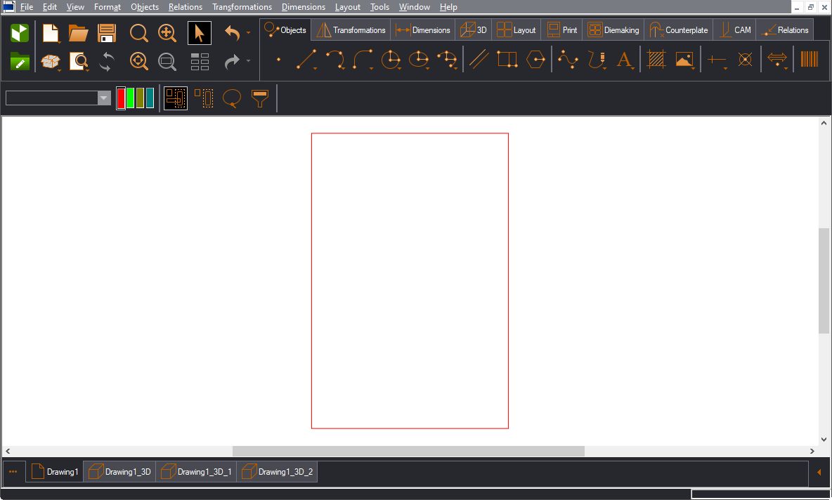
The procedure starts in the 2D area, where we create a 3D guideline object that EngView will use to perform cylindrical bending in the 3D area.

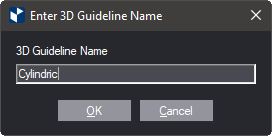
The Enter 3D Guideline Name dialog box appears.
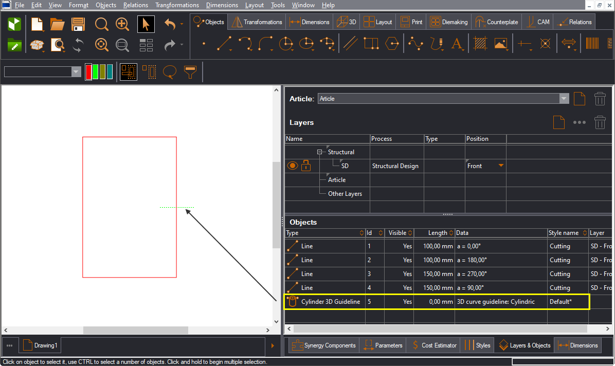
The Cylinder 3D Guideline object is now named Cylindric. You see it in the Layers & Objects tab and in the 2D area.
After creating the guideline object, we move to the 3D area, where we perform the bending.
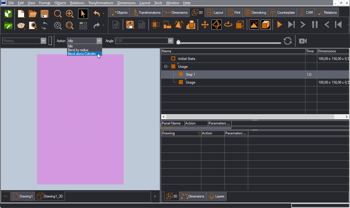
The plane is now ready for bending.
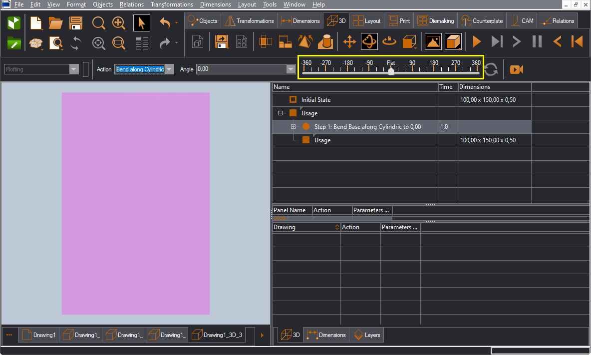
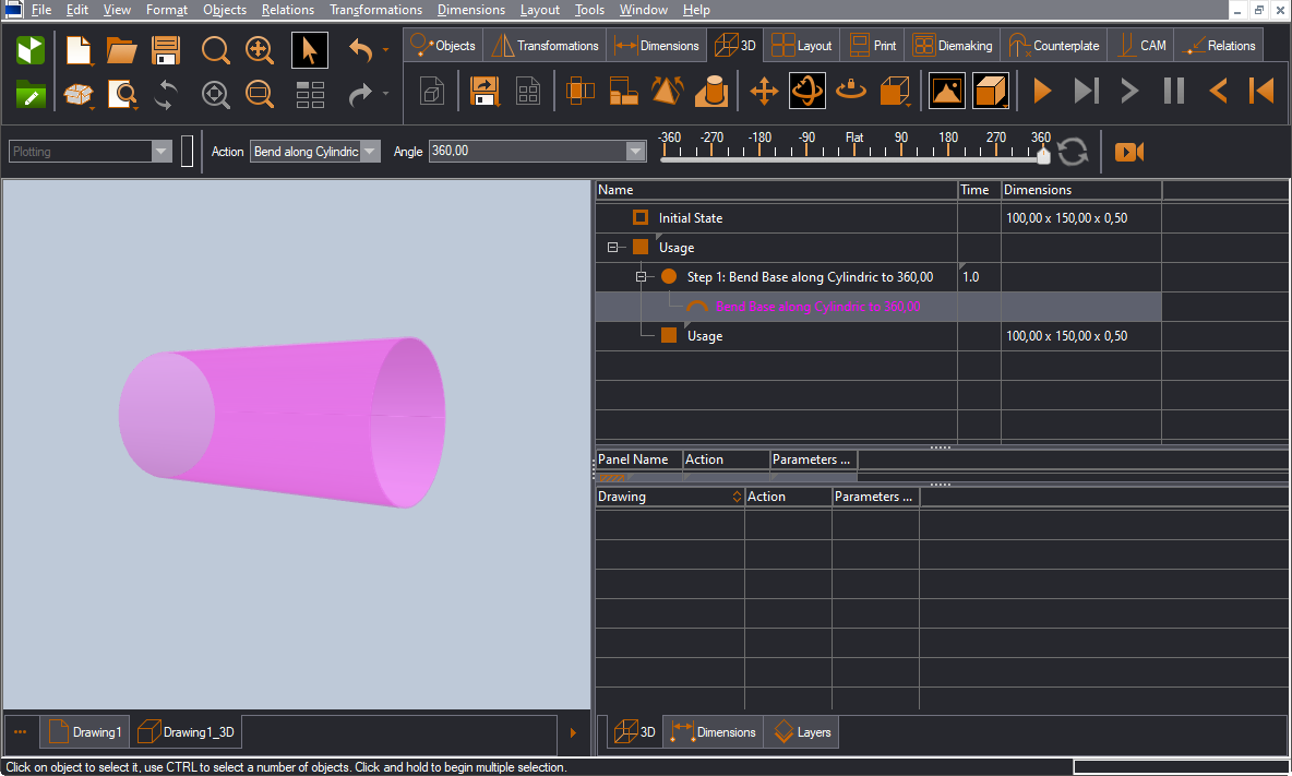
To bend the panel to a full cylinder, drag to 360 degrees. This means the bending will be along a 360-degree sweep:
To bend the panel to a partial cylinder, set a smaller sweep:
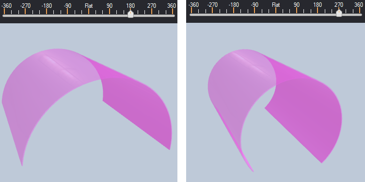
NOTE: The different sweeps define different cones. The reason is that a sweep determines the part of the cylinder that is covered by the guideline object in the 2D area.
NOTE: You can now set the edge that EngView will use to execute the bending. The position of the guideline determines the direction in which the panel will bend. In the pictures below, circles mark the places along the guideline at which EngView executes the bending.