The Solver is the tool that runs through a calculates geometric constructional tasks according to the predefined dimensions and geometrical relations between objects. The Solver ensures that there are no constructional disagreement — that is, that, in a design, the relations and dimensions between a design's objects meet the geometric constraints needed to produce a geometric figure.
You can use the Solver only when you are creating base and single components.
Depending on the set relations, dimensions and parameters, the following types of drawing are possible:
======
 Recalc Drawing Recalculates the
current drawing according to changes made in it. NOTE: Use this button
after you have stopped the Solver and have made some drafting changes.
Recalc Drawing Recalculates the
current drawing according to changes made in it. NOTE: Use this button
after you have stopped the Solver and have made some drafting changes.
 Stop Solver When the button is
pressed in, the program does not calculate the drawing until you click
Recalc Drawing .
When the button is not pressed in, the
Solver is in operation and the drawing is calculated after each drafting
change. NOTE: Usually, the constant calculation of the drawing after each
drafting change alters the drawing's shape in a way that may make it difficult
for you to follow. Use this button when you do not want the Solver to
constantly calculate the drawing, and when you have finished drawing,
launch the Check Geometric Assumptions
functionality.
Stop Solver When the button is
pressed in, the program does not calculate the drawing until you click
Recalc Drawing .
When the button is not pressed in, the
Solver is in operation and the drawing is calculated after each drafting
change. NOTE: Usually, the constant calculation of the drawing after each
drafting change alters the drawing's shape in a way that may make it difficult
for you to follow. Use this button when you do not want the Solver to
constantly calculate the drawing, and when you have finished drawing,
launch the Check Geometric Assumptions
functionality.
 Static components Used for auxiliary
components that you do not need well constrained.
Static components Used for auxiliary
components that you do not need well constrained.
 Check Geometric Assumptions Checking
for geometric assumptions across the drawing. The functionality displays
reports when information is missing about the positioning of objects and
control points — this leads to more than one solution for constructing
the geometric figure.
Check Geometric Assumptions Checking
for geometric assumptions across the drawing. The functionality displays
reports when information is missing about the positioning of objects and
control points — this leads to more than one solution for constructing
the geometric figure.
When you draw a base or a single component, the Solver checks the dimensions and geometric relations between the objects you draw and ensures that they produce a correct drawing.
To check for geometric
assumptions, click Check Geometric Assumptions
.
Solver messages
Once a drawing is well-constrained, the following message appears.
Assumptions
If the set relations and dimension are not enough, for the construction of the geometric figure, the Solver begins to list the geometric assumptions by highlighting the problem objects and offering solutions. An assumption is offered in a dialog box, such as the following:
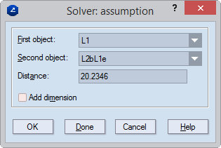
First, second object The First and Second object lists display the objects about which an assumption is made. Often there is more than one choice for an assumption, and you can choose the objects from the drop-down lists.
NOTE: If the First and the Second objects are non-parallel lines, the Solver offers a dimension for the angle between them. If the two objects are points, the Solver offers a dimension for the length of the line segment between the two points.
In the example above, the Solver assumption is that the angle between the lines L1 and L2 is 20.2346 — as detected according to the current situation of the two lines. If you want the parallel distance dimension detected, you can enter another value for it, and then select the Add dimension check box.
[Parallel Distance | Distance | Acute Angle] Displays the type of dimension to be set.
Add dimension Adds an active dimension for the distance or angle in the assumption. This makes the respective assumption a permanent dimension. NOTE: You do not need to create the dimensions that the Solver suggests. You can use the information as reference, and then decide how to dimension the drawing.
OK Proceeds to the next assumption, if there is any. NOTE: If the Add Dimension check box is selected adds the suggested dimension.
Done Closes the dialog box.
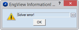
When during drawing an operation is carried out that will prevent the drawing from being well-constrained, a Solver error message appears. Errors appear most frequently (1) when a relation and a dimension run counter to each other, or (2) when two dimensions are in a conflict.