 .
.By using design alignment you can position the design in relation to the coordinate system of the samplemaking machine. You can align the drawing by:
To use design alignment
.The Coordinate System Alignment dialog box appears.
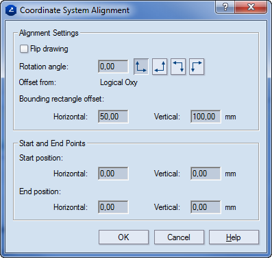
Alignment settings Sets how the drawing is positioned. The default positioning is by common origin mode, with zero values in Offset and Rotation angle. In this case, the drawing is positioned in its original position, without any additional alignment corrections.
IMPORTANT: Alignment takes place in reference to the control point located at the lower left vertex of the bounding rectangle of the drawing.
Flip drawing Flips the drawing into a mirror image.
Bounding Rectangle Offset Sets the absolute offset coordinates, X and Y, between the original and the new positions of the drawing; this is the offset between the origin of the coordinate system of the CAM drawing and the control point of the bounding rectangle of the structure in the CAM drawing. (The control point is located at the lower left vertex of the bounding rectangle.)
Rotation angle Sets the rotation angle by which the bounding rectangle of the drawing should be placed on the samplemaking machine in reference to the coordinate system of the CAM drawing. Enter a value or click a rotation-direction button.
 In the CAM drawing, rotates the 1up by 0, 90, 180 and 270 degrees, respectively.
Start & End Points Sets the starting and end points of the tool.
Start position Sets the absolute coordinates, X and Y, of the starting position (zero point) of the tool head (the place where the tool head will be positioned before the start of the processing). The starting position is displayed on the screen by a green dot  . You can reposition the starting point by dragging the dot manually on the screen.
End position Sets the absolute coordinates, X and Y, of the end position of the tool head (the place where the tool head will stop when the tool path processing has been completed). The end position is displayed on the screen by a blue dot  . You can reposition the end point by dragging the dot manually on the screen.