 Places the bridges at equal intervals along the object.
NOTE: The following procedure describes how a bridge template is created. The procedure for editing a bridge template is analogous, the only difference being the clicking of Edit in Step 2.
The Manage Bridge Templates dialog box appears.
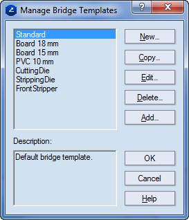
NOTE: If you want to edit an existing template, select it, and then click Edit.
The Edit bridge template dialog box appears.
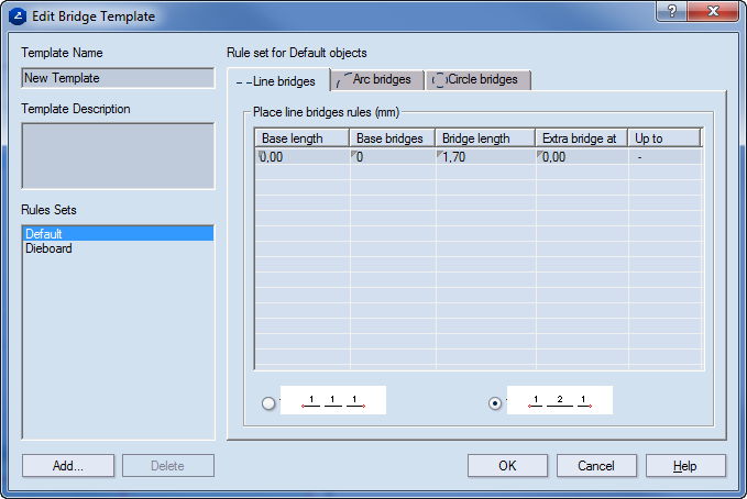
Template Name Sets the name of the bridge template.
Template Description An optional description of the template.
Style rule sets Displays a list of the available sets of bridge placement rules. A set comprises the bridge placement rules for a particular style — for example, Cutting 1.5pt, CutCrease 3x5. The rule sets Default and Dieboard are built-in in all bridge templates. Unless a rule set is defined for objects in a particular style, the Default rule set is applied.
Rule set for dieboard objects Set the rules for the objects to which the Dieboard style is assigned.
Line bridges Sets rules for the placement of straight-segment bridges.
Arc bridges Sets rules for the placement of curved bridges.
Circle bridges Sets rules for the placement of circular bridges.
Place line bridges rules (mm)
Base length Sets the lower threshold of the interval whose upper threshold is marked in the Base length value of the next row in the table. NOTE: Although the upper threshold of the interval is determined in the next row, the number of bridges that will be placed in the interval is displayed in the table row in which the lower threshold. For details about how bridge placement rules are created, see Creating bridge placement rules.
Base bridges Sets how many bridges will be placed within the set segment length.
Bridge length Sets the length of the bridges that will be placed on the set segment.
Extra bridge at Sets the interval at which an extra bridge will be placed on the segment.
Up to Displays the total number of bridges for the set interval.
Places the bridges at equal intervals along the object.
 Places the bridges at equal distances along the object and at half-length at the ends.
NOTE: The division of the object into intervals begins at the object's center.
Bridge nicks options Dieboard rule set only. Due to specifics in the cutting of a dieboard, these are the properties of nicks on the dieboard.
 Sets the angle of the nicks.
 Sets the height of the nicks.
NOTE: The Default rule set is applied for all situations which are not covered by the rule sets in the list.
The Add rules for style dialog box appears.
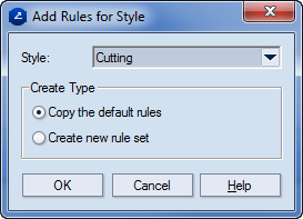
Style Displays the style for which rules will be created in a set.
Create type Defines how the new rule set will be created — on the basis of the default rule set, or by creating an empty rule set.
The name of the rule set that you created appears in the Style rule sets list.
— and height — .