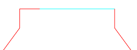
The nick as marked in the bridges drawing
In an exported file, the gap indicates the place on the cutting contour where the digital machine does not cut the media.
Nicks are notches made on the cutting rules to prevent the cutting of the media at the respective locations. The resulting uncut sections ensure that despite having being cut, the media remains in one piece and can be moved on further to the next sections stages of the converting process. The nicks can be made manually, by means of a nick grinder, by a rule-bending machine, or with digital machines.
In Package Designer you can use three types of nicks:
|
|
|
|
The nick as marked in the bridges drawing |
In an exported file, the gap indicates the place on the cutting contour where the digital machine does not cut the media. |
|
|
|
|
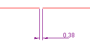
The nick as marked in the bridges drawing |
The visual division indicates the place on the cutting rule where a notch will be made by the rule-bending machine. |
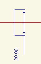
The position marker (in black) as it appears in the bridges drawing. The marker's length is the actual length of the marker on the dieboard.