Use Case: Creating an EngView
project out of a multi-page pdf file with applied artwork
This use case focuses on how to create a 3D model of a multi-part
product from an imported multi-page pdf file.
Examples of such structures are displays.
Goals of the procedure
The procedure presents how you can use the EngView-Illustrator
integration to:
- EngView
structural drawings out of a multi-page pdf file.
- A 3D representation of the multi-part structure with the graphic
designs applied to it.
Structure of the procedure
The procedure consists of three steps:
- In Illustrator, you open the multi-page pdf file and create
an EngView
structural layer. In EngView,
(1) you assign the correct production styles (most often Cutting
and Creasing) to the product' structural objects, (2) check the
structures for drafting errors, (3) create individual 3D drawings
for each part and then (4) create a final 3D model assembled from
all the individual 3D drawings.
- Finally, in Adobe Illustrator, you view the assembled 3D model
with its artwork (graphical design).
top of page
I. Creating the EngView
structural layer
The critical factor here is that the integration does not recognize
the lines that are meant for the structure (i.e. cutting, creasing,
perforation). Making them recognizable by EngView
is essential for the creation of a 3D model. This step tells you how
to extract the structural objects from the original design in order
to create an EngView
structural layer.
- Open the file in Adobe Illustrator.
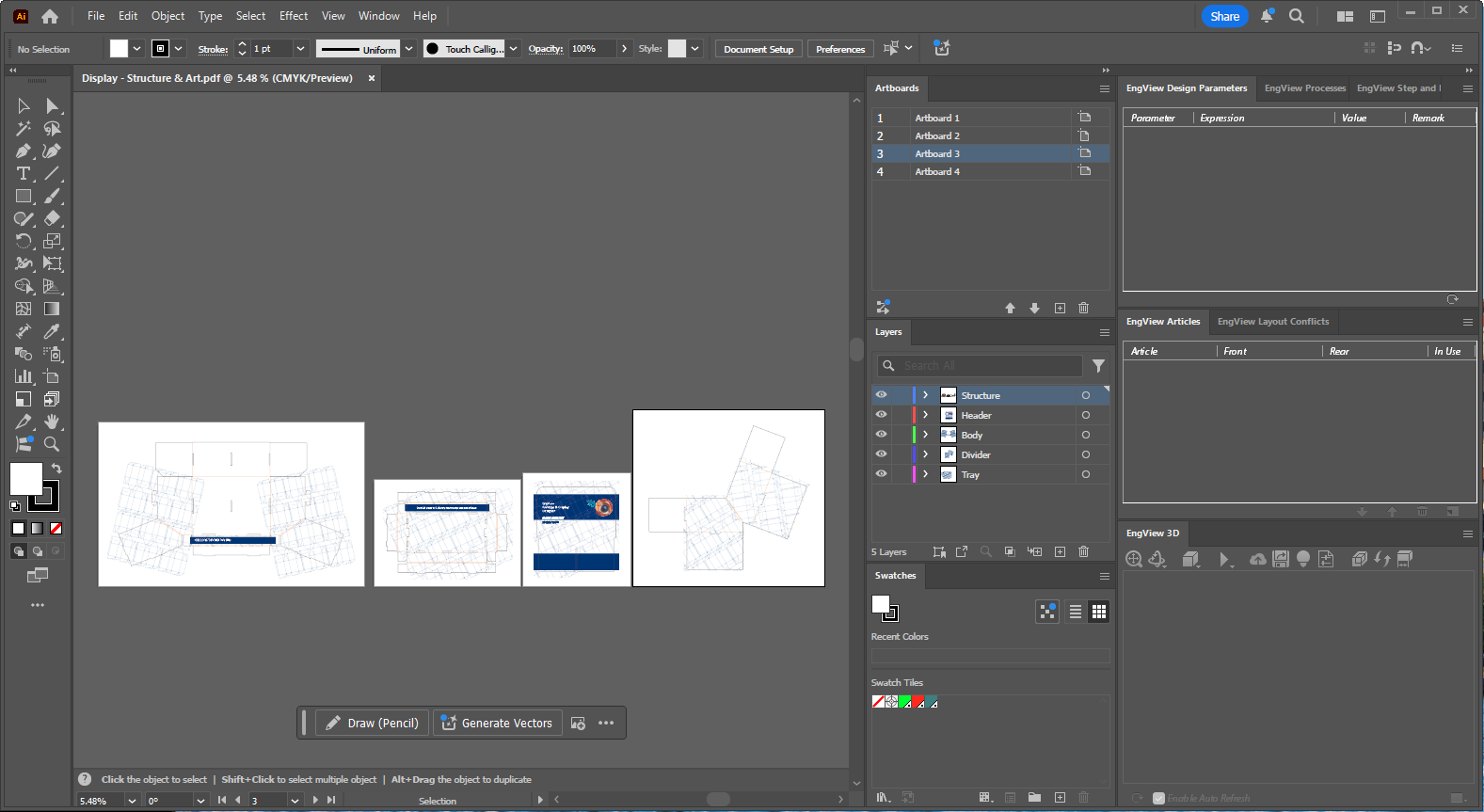
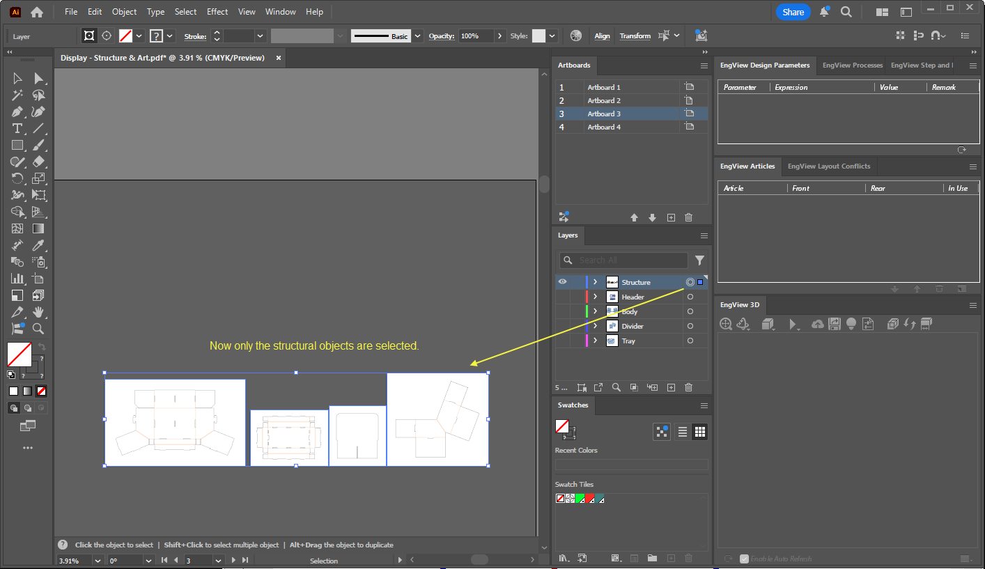
- Next we select the structural objects. Select all objects related
to the structure of the product in all artboards simultaneously.
- Select all the structural objects in a single artboard.
- Repeat Steps 2 and 3 for each artboard.
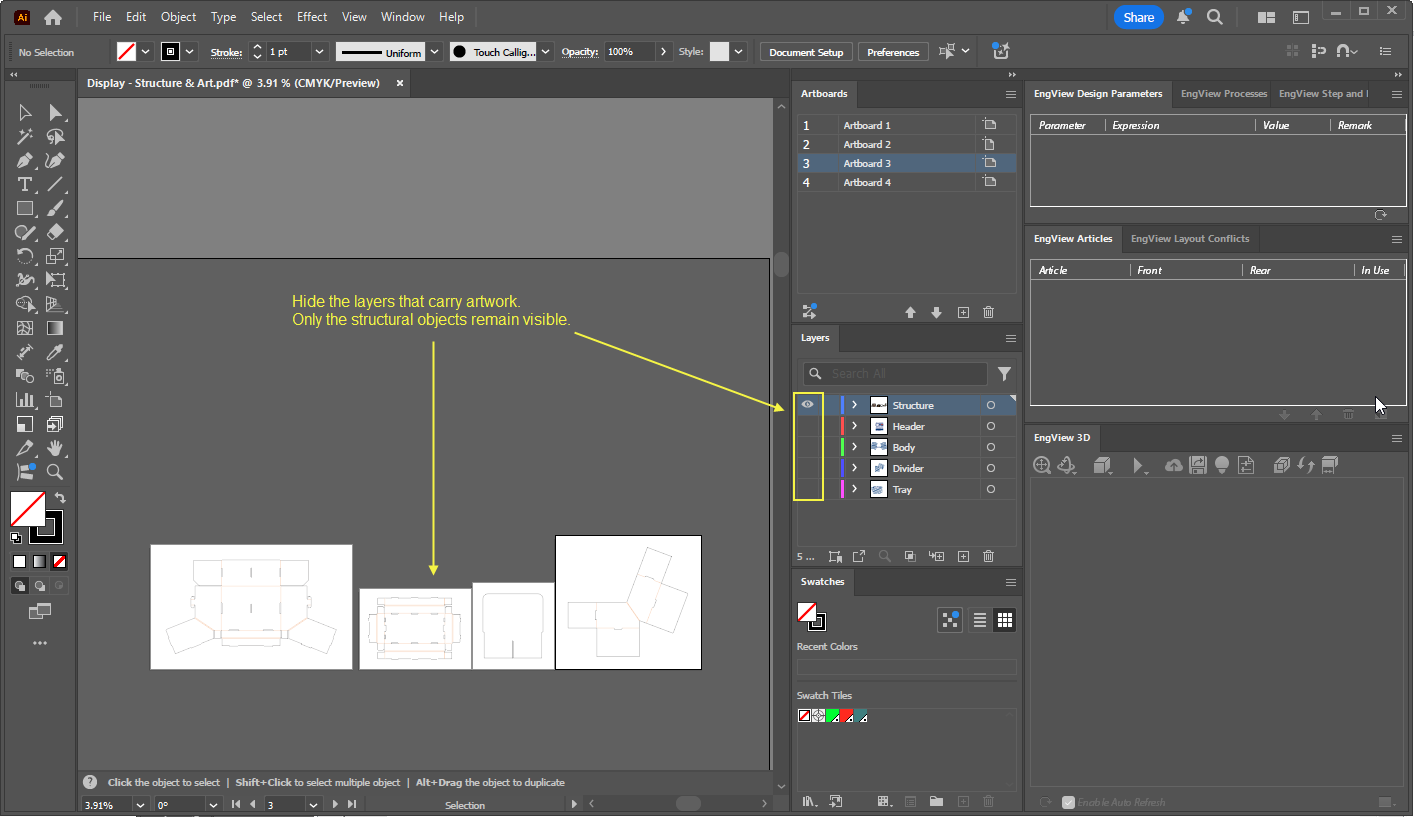
The artwork is now not visible; only structural
objects are visible.
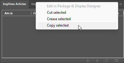
- In the EngView
Articles panel, click the menu icon, and then click Copy Selected.
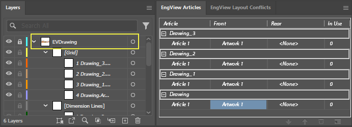
An EVDrawing layer has been created. It contains
all the structural objects. Notice also that articles that carry the
artwork (graphical designs) for each artboard have been created in
the EngView
Articles panel.
- From the artwork-related layers, delete (or hide) the original
structural objects (those selected in Step 2). These objects are
not meant for printing.
top of page
II. Moving to EngView
to assign styles to objects and create an assembly 3D model
We now move to EngView,
where we will: (1) assign the correct styles to the structural objects,
(2) check the structures for drafting errors, (3) create 3D drawing
for each 1up drawing, and (4) create the assembled 3D model of the
final product.
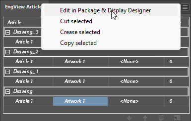
- In the EngView
Articles panel, click the menu icon, and then click Edit in
Package & Display Designer.
EngView
opens. We see a project with as many 1ups (2D drawings) as the Illustrator
artboards. In most cases, the drawn objects are copied in styles for
EngView as
they come from external software.
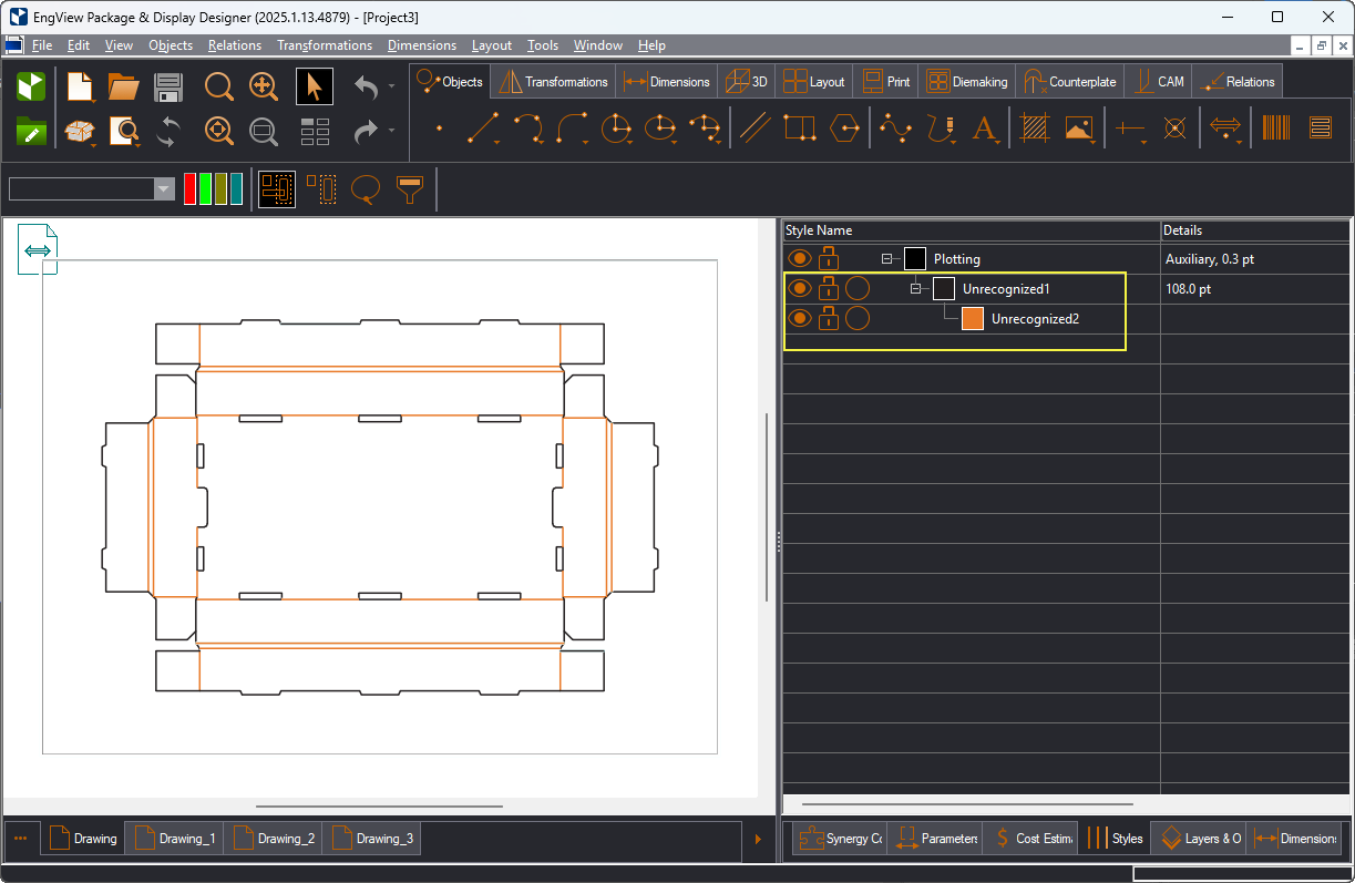
To create 3D drawings out of the 1up drawings, EngView
needs to recognize the styles as productional (most often Cutting
and Creasing). To achieve this, we will assign EngView
styles to the 1ups' objects.
- For each 1up drawing repeat Steps 5–7:
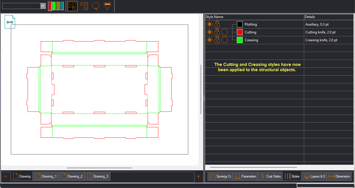
- In the graphical area, select the objects that will be cut,
and assign them to the Cutting style. Then select the objects
that will be creased, and assign them to the Creasing style.
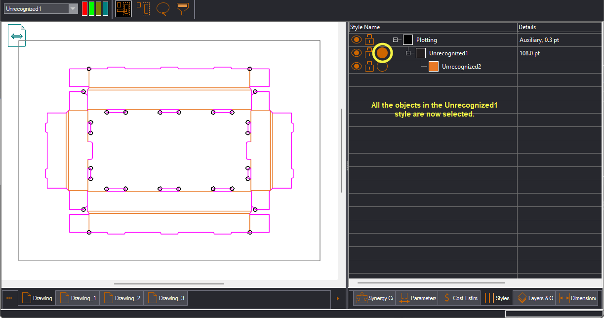
Selecting the original objects which EngView refers to as Unrecognized1.
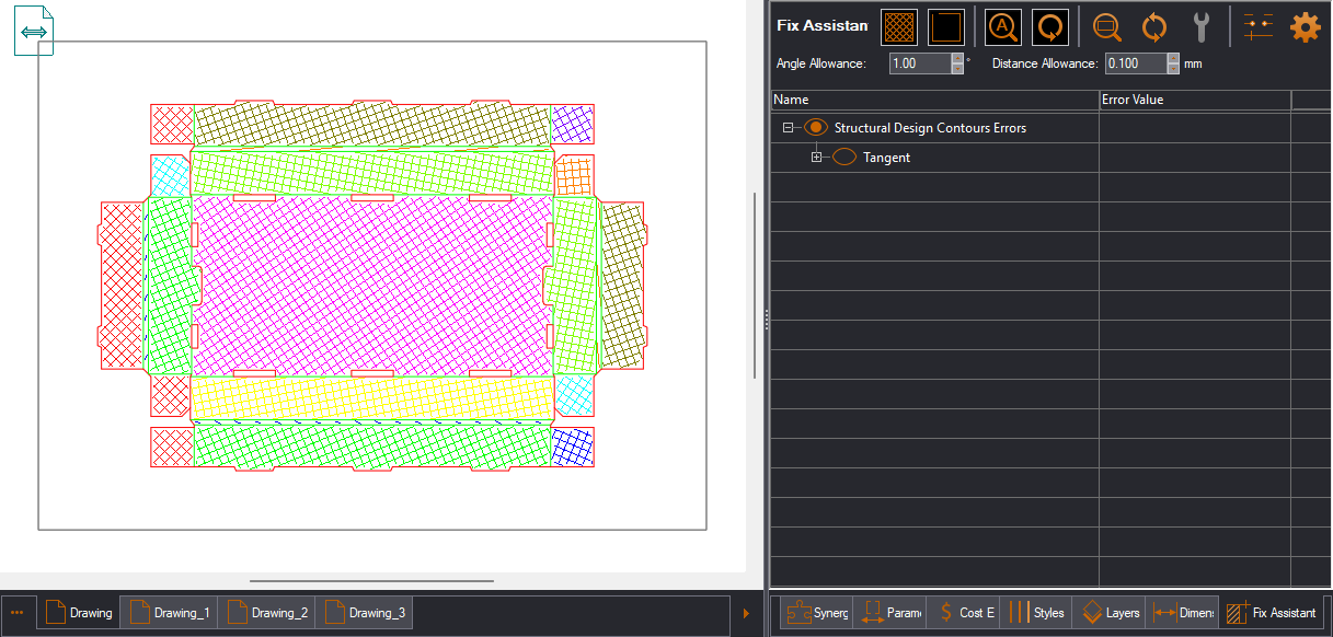
- Check for drafting errors with Fix Assistant. For the 3D representation,
it is especially important that the panels in the drawing have
closed contours. To ensure you have closed contours, use the Fix Assistant
tool.
- When you have associated the cut and crease objects with their
styles and the 1up drawing has no critical drafting errors, in
the 3D tab, create a 3D drawing for each 1up drawing.
- Assemble the 3D model for the final product.
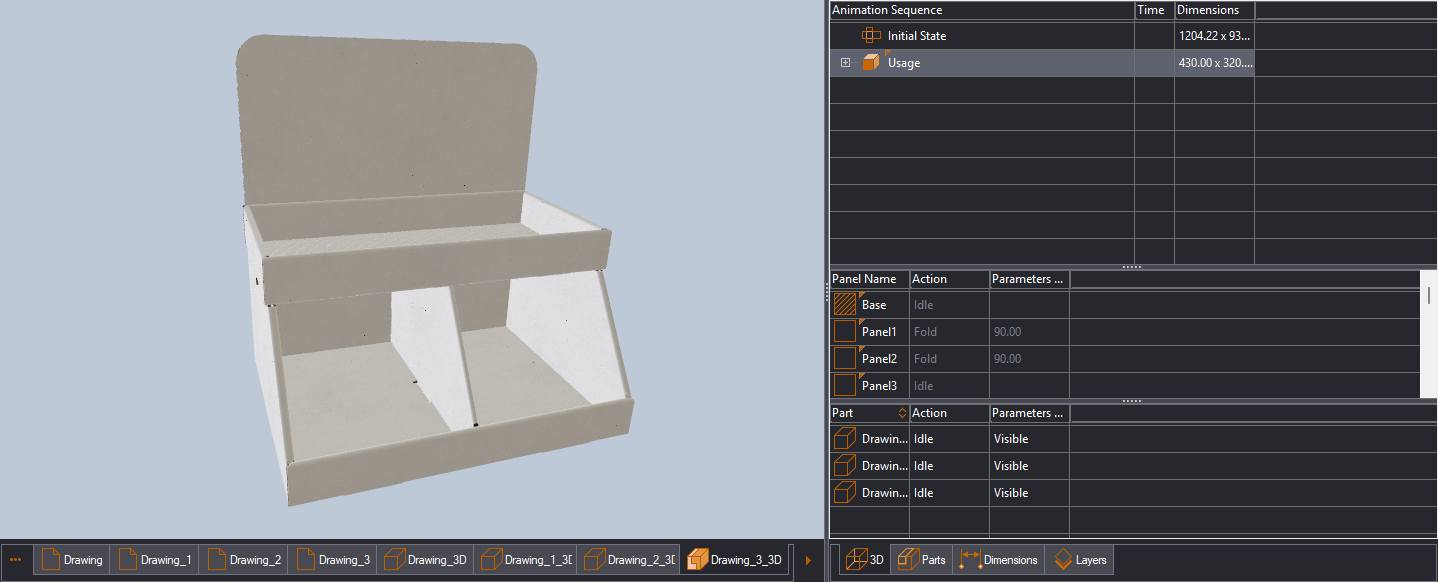
- When the 3D model is ready, save the file and close it. The
integration takes us back to Adobe Illustrator.
top of page
III. Moving Back to Adobe Illustrator
In the EngView
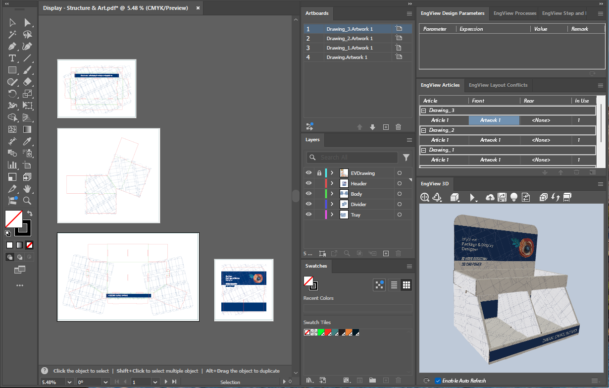
3D panel in Illustrator, you now see the 3D model that you created
in EngView.
In the Layers panel, enable the layers that carry the artworks to
see how they sit on the product's surfaces.