=================================
Placing print marks in a dedicated layer
=================================
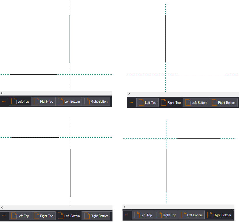
Print mark standards are .evd files that contain drawings of each print mark that you want to position. The following picture displays the Crop Marks standard, which comes automatically with your installation. The standard contains four print marks, each of them in its own drawing — Left-Top, Right-Top, Left-Bottom, and Right-Bottom.
An EngView installation comes with eight predefined print mark standards:
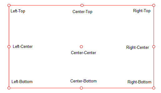
Print marks can be placed at nine positions along a bounding rectangle — on the cut box, the sheet's margins, the sheet's edges, the dieboard's margins, or the dieboard's edges:
You draw each individual print mark in a separate drawing. That is why each print mark standard can have up to nine drawings.
To create a print mark standard
NOTE: You do not need to create drawings for all nine print mark positions.
IMPORTANT: Name the print mark drawings exactly as shown in the above picture. This guarantees that the program will recognize the drawings and will position them at the right place along the bounding rectangle.
When you are drawing the print mark, keep in mind the center of the coordinate system. When applying the mark, the program attaches it by using the origin of the mark's drawing's coordinate system. If for some reason you do not want the print mark to begin at the point of attachment, you can leave an empty space between the origin of the coordinate system and the beginning of the print mark. This is especially useful when the drawing uses bleed. Since bleed is not part of the bounding rectangle and spills over the area of the 1up, it makes sense to position the print mark outside the bleed area.
IMPORTANT: The drawing name determines which quadrant of the coordinate system will be treated as inner/outer of the referenced bounding rectangle against which the print marks will be aligned.
Consider the Crop Marks.evd print mark standard (the crop marks are aligned along the cut box) and a Registration Marks standard (dots are aligned along the sheet's edges):

You can draw the print marks:
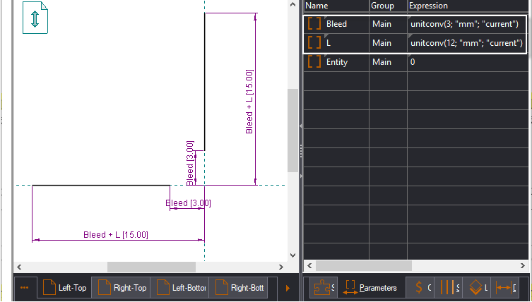
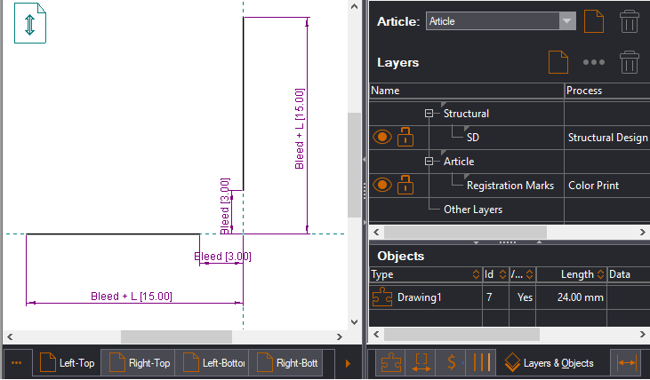
IMPORTANT: All EngView-distributed standards are parameterized — that is, resizable components were used as basis for them (pictured in the left drawing), whose sizes are controlled by parameters (pictured in the right drawing). Note how two parameters are used to control the distances of the bleed (Bleed) and the print mark's length (L).
You must set the Entity parameter, which defines the bounding rectangle along which the print mark will be aligned. There are five options for aligning print marks along:
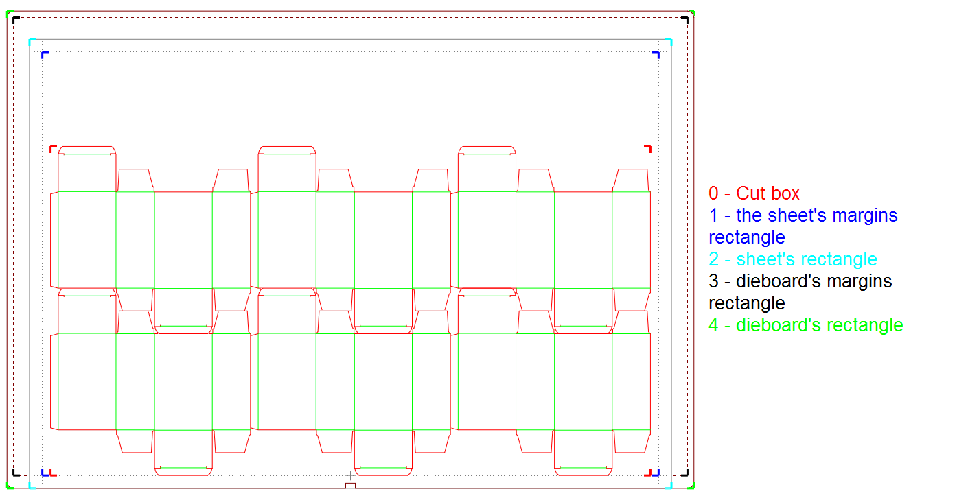
The following table lists the values that the Entity parameter can have depending on the rectangle you want the print mark aligned along:
Values of the Entity parameter
| To extract | Use |
|---|---|
| 0 | THE CUT BOX |
| 1 | THE SHEET'S MARGINS (SHEET INNER RECTANGLE) |
| 2 | OUTSIDE THE SHEET’S EDGES (SHEET OUTER RECTANGLE) |
| 3 | THE DIEBOARD’S MARGINS (DIEBOARD INNER RECTANGLE) |
| 4 | THE DIEBOARD’S EDGES (DIEBOARD OUTER RECTANGLE) |

IMPORTANT: If you do not set an Entity parameter for a drawing, the respective print mark will not appear when you start applying the standard. The reason is that the program will not be able to place the print mark on a particular rectangle. The same applies if you have set a print mark to be attached to a sheet or dieboard edges, but there is no sheet or dieboard positioned in the drawing — in this case, the print marks set for the sheet and dieboard bounding rectangles will not appear on the screen.
Using the Entity parameter across a standard
When you create the Entity parameter, it is a local, set for each drawing in the standard file. This means that you can set — for example, the Left-Top print mark at the dieboard's inner rectangle and the Center-Top print mark at the sheet's outer rectangle.
If you want to set all the print mark drawings in the standard file with identical alignment, set the Entity parameter for one of the drawings, and then make it global. This guarantees that all the print marks are positioned as per the value of the Entity parameter.
Assigning print marks to their own layer is not obligatory but is highly useful in pre-production-related tasks. For example, when working with the integration with Illustrator, you may need to hide the print marks to prevent them from appearing on the final product. When they are placed in a separate layer, switching them off is easy in Illustrator's Layers panel.
You can place print marks into a separate layer while creating a standard or while creating a template.
To place print marks to a separate layer
IMPORTANT: When you create a standard, make sure you save it in the Standards subfolder of the dedicated folder. This guarantees that EngView will access it when you begin applying the standard onto a 1up of layout drawings.