The straightforward way of constructing a box is by attaching compound components to a base. To ensure that the relations between a compound component and its base are correct, the program uses a set of auxiliary system parameters that guarantee that, once attached to the base, a compound component will be correctly computed each time when the base is edited. These system parameters, called AX parameters, are part of the compound component and are associated with the distances in the base that are determined by its active control points. Due to this association, while a compound component is being attached to a base, the values of the component's AX parameters take the values of the base's main distances. This guarantees that each time the base is edited, the compound component will be automatically recomputed to reflect the changes in the base. When a component has been attached to a base, its AX parameters are lost, as it were, because they have adopted the values of the parameters in the base to which they had been associated. Consider the example in Picture 1:
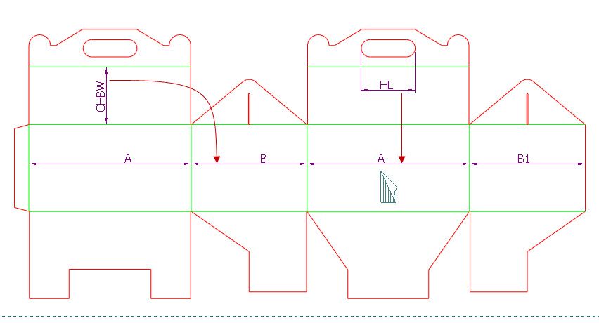
PICTURE 1. The parameters CHBW and HL belong to the compound component and are dependent on the parameters B and A, respectively, in the base. Originally, CHBW and HL were dependent on the AX parameters in the component, which, after the compound component has been attached, have taken the values of the base's parameters B and A.
Take a look at the following compound component created for a four-panel box.
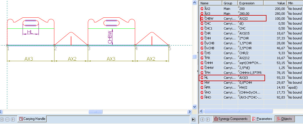
PICTURE 2. A ready-for-use compound component
The AX parameters are named AX1, AX2, AX3, ... AXN. In the base, they are associated with the active control points as follows:
AX1 is the distance between the first and the second control points — that is, the first and the second clicks during the attachment of the component.
AX2 is the distance between the second and the third control points — that is, the second and the third clicks during the attachment of the component.
[...]
Parameter AXN is the distance between the last but one and the last control points — that is, the last but one and the last clicks during the attachment of the component.
In four-panel boxes, the sizes of the middle panels — panels 2 and 3 — correspond to the main length and width of the box. That's why in the compound component the distances between the second and the third control points is linked to the parameter AX2, and the distance between the third and the fourth control points with the parameter AX3.
Linking compound components with the base
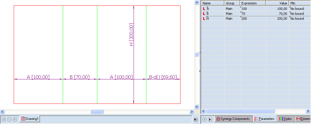
PICTURE 3. The parameter A has a value of 100; the parameter B a value of 70.
Drag the 02 Carrying Handle compound component, and attach it to the base.
When the compound component has been attached to the base, the table in the Component Properties dialog box shows the substituted parameter values.
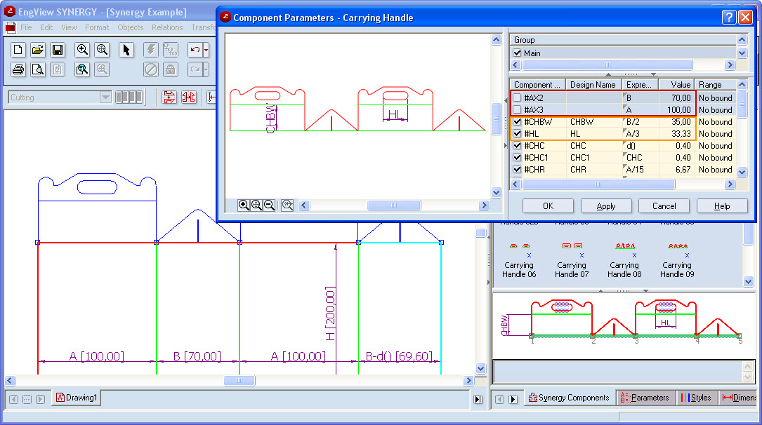
PICTURE 4. AX2 and AX3 are substituted with parameters B and A (highlighted in red).
During the attachment of the component the program takes into account the distances between the second and the thirds clicks, and between the third and the fourth ones — these distances are reflected as values for AX2 and AX3. Since in the tabular area there are already parameters with the same values (A and B), the program links the AX2 and AX3 parameters with the parameters B and A, respectively. In this way, the parameters dependent on AX2 and AX3 in the compound component (CHWB and HL) are now dependent on the parameters B and A, respectively. This guarantees that every time the values of the parameters A and B are edited, the box's top will be correctly recalculated.
As a result, the parameters CHBW and HL (highlighted in green), which are dependent on B and A, respectively, will be correctly recalculated every time B and A are edited.