Tools Read-only. This property pertains only to child tools.
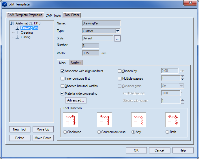
Type Sets a type for the tool. Preset types include Router, Laser beam, Water jet, Cutting knife, Creasing wheel, V-cut, Matt cut, and Pen. Custom lets you set a new type.
Name Displays name of the selected tool in the preview area on the left.
Style Displays the style used to display
all objects processed with the new CAM tool in the tool path. To set a
different style for tool viewing, click the browse button  .
.
Number Sets the number of the new tool as corresponding to the consecutive numbers of the tools on the "real" machine. You can also change the tool number later when you generate the NC script file directly in the NC Generation Properties dialog box.
Width Displays comments attached to the currently selected template.
Style Displays the style that the program
will use to display all objects processed with the new CAM tool in the
tool path. To set a different style for tool viewing, click the browse
button .
Style Default means that there is actually no style selected — that is, None in the Edit Style dialog box. Use this technique if you want to set only a color to a certain object type, without associating it with a specific style.
The Main tab
Associate with align markers Associates the current tool with the align markers. Such can be, for instance, cut or creased, depending on the tool that they are associated with.
Inner contours first Generates a tool path in which the current CAM tool starts processing the inner objects first. For example, if you make a CAM sample of a packaging box with an inscribed ellipse in one of the sides, cutting the outer contours first would leave the cutting of the ellipse for the end of the cutting tool use. As a result, the sheet will not hold so steadily on the samplemaking machine.
Observe line/width tool widths Makes visible the widths of lines or tools.
Material side processing Sets properties for processing of the material. These include the side on which the cutting will be done, the lead-in and lead out settings, and the directions of processing for the inner and outer sides. To edit the settings, click Advanced, and then in the dialog box that appears edit the settings.
Shorten by Shortens the creasing objects by a certain distance, so that the creasing wheel stops before the end of the creasing lines. This prevents the damage in the 1up to creasing regions which are adjacent to the creasing lines. In the edit box on the right, enter the distance, in the current metric units, by which you want to shorten the creasing objects.
Multiple passes Performs multiple creasing on objects. Enter a number of passing of the creasing tool. Value range: [0–3]. This is very useful in some cases when the material is tougher - the creasing objects must be processed a couple of times, so that they are easier to fold later.
Consider grain Defines if the grain direction is along the Ox or Oy coordinate axis, depending on the sheet placement.
Angle tolerance Defines the maximal angle by which the creasing tool should be allowed to veer off from the Ox/Oy grain direction, respectively.
Objects with grain Sets a special number of creases for the objects processed with grain direction. Usually this number will be smaller than the number in the Multiple crease check box. Thus you can make a difference (in terms of multiple creases) between the creasing objects processed with grain and the ones processed against grain. Value range: [0–3].
Tool Direction Sets the direction for the outside contour to be processed.
Clockwise The outside contour is processed clockwise.
Counterclockwise The outside contour is processed counterclockwise.
Any Package Designer sets the outside-contour direction randomly, either clockwise or counterclockwise.
Both The outside contour is processed both clockwise and counterclockwise.
The Custom tab The properties in this tab are created during the setting of the properties of the machine. Here you can only edit their values as you need them for the work at hand.
Name Displays the name of the custom property. Check the custom properties that you want the child tool to inherit from the "parent" primary tool. Read-only.
Value Sets the default value of the custom property.
Units Sets the default units.
Visible Comment A field for comments on the custom properties.
Settings for V-Cut are managed differently than those of the other CAM tools. To begin setting them, in the CAM Tools tab, click the V-Cut tool, and then edit the settings as you want them.
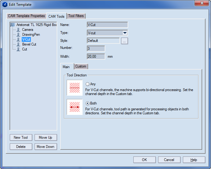
The Main tab
Tool Direction
Any. Automatic optimization of the tool path is done. To specify channel depth, click the Custom tab. NOTE: The reverse V-Cut move does not need to follow immediately the forward one.
Both. The machines carries out both the V-Cut and the reverse moves.
The Custom tab
The settings for each V-Cut tool are set in the Custom tab.
NOTE: You can create the properties in this tab are created while setting the properties of the machine. Here you can only edit their values as you need them for the work at hand.
Name Lists the name of the tool.
Value (Editable) Lists the value given to the tool.
Units The current units.
Visible (Editable) Shows whether the property will appear in the tabular area (the CAM Tools tab). The options are Yes and No.
Script access (Editable) Sets how the script will handle the tool's Value setting. The options are:
Read-only The script uses the value of the property as it is defined by the CAM template, making no changes to it during the job.
Local Only During the job the script dynamically makes changes to the value of the property, which are lost when the job is completed.
Committable During the job the script dynamically makes changes to the property value. When the job is completed, the changes are saved into the CAM template and are taken into account when the next job is started.
Comment (Editable, Optional) Notes about the tool.