You can construct a chamfer between two nonparallel lines by trimming the angle between them (or their projections) with a straight line that is opposite to the angle in the formed chamfer triangle.
A. Two intersecting lines B. A chamfer is constructed at the point of intersection of the two lines.
In the process of drawing and when selected.

Relative Dx and Dy while repositioning the chamfer.

A chamfer has three control points: the starting and end points of the chamfer line and the vertex of the angle where the two lines that define the chamfer intersect.

note: In the graphical area, to see the Back A and Back B of the chamfer, rest the pointer over the chamfer line.
When you have finished drawing a chamfer, its object type, Id number, length, the angle between Back A and the chamfer, and the style of the chamfer are recorded in the Objects tab in the tabular area.
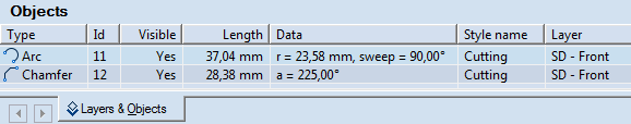
The data in Objects tab in the tabular area is unavailable for direct editing.
To draw a chamfer
NOTES: (1) You can construct a chamfer only between straight-line segments. (2) You cannot construct a chamfer between parallel lines.
 .
. .
.NOTE: You can skip this step and still construct a chamfer between the two objects. However, the line that you'll have drawn will be treated as a simple line, not as a chamfer. (Note the indication in the tabular area.)
A sample image of the fillet appears, following the motion of the mouse. Non-intersecting lines are automatically extended until they intersect; then a chamfer is constructed between them.
To modify a chamfer by changing its attributes
To reposition a chamfer by dragging
note: During drawing or repositioning a chamfer, when you enter a value in Angle, Back A or Back B while drawing, or in Dx or Dy while repositioning, and then move to the next edit box, for example, by pressing TAB or ENTER, Package Designer limits the scope of the chamfer preview according to the specified value. Consider the following example:
If you start drawing a chamfer, enter a value of 60 mm for Back A and press TAB to move to the Back B, when you point to further define the chamfer position Package Designer lets you only to move the mouse pointer so that the defined Back A length of 60 mm is kept. To drag the object preview freely, go back to the respective edit box (Back A or Back B, Dx or Dy, but not Angle) and enter 0.00, and then press TAB to move to the next edit box.
The zero-value rule is valid only for distance values and not for angles, circle diameters, arc radii and radii of auxiliary circles inscribing or circumscribing regular polygons. It applies also to all contextual edit bars for definition of relative Dx and Dy values.
To delete a chamfer
Select the chamfer.
Press CTRL+DELETE.
The objects between which the chamfer was constructed are restored.