You can edit rectangular areas to alter the parts which will fit in them, the types of parts which will fit in them, the size and position of the areas on the design frame, as well as the scaling of the parts.
To edit a design frame
The design frame drawing appears as a separate project.
The Design Frame Part Properties dialog box appears.
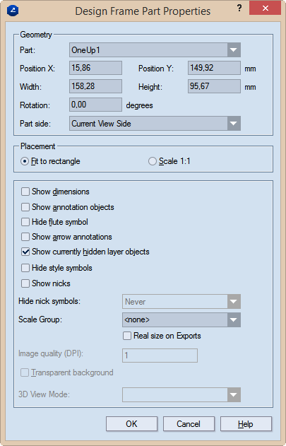
Geometry Settings for the part's size and position
Part Sets the part type (1up, layout, 3D) to be inserted by default in the current rectangular area when you use the design frame to create a print drawing.
Position X Sets the position of the part along the x-axis.
Position Y Sets the position of the part along the y-axis.
Width Sets how wide the rectangular area will be.
Height Sets how tall the rectangular area will be.
Rotation Sets the angle at which the part will be rotated in the rectangular area.
Part side (1up and layout drawings only) Sets the side that will be displayed in the rectangular area. The options are: Current View Side, Front, Rear, Diecutting, Counterdiecutting.
Placement Sets specifics of how the part is placed onto the
Fit to rectangle Makes the part fit into the positioning rectangle in the design frame.
Scale 1:1 Places the part without scaling.
Show dimensions Makes visible, in the printed document, the dimensions in the 1up and/or layout drawings.
Show annotation objects Makes visible, in the printed document, any notes added to the 1up drawing and part of the Annotations layer.
Hide flute symbol Does not display, in the printed document, the symbol that indicates the direction of the flute or grain.
Show arrow annotations Displays the arrow annotations. NOTE: The Show annotation objects check box must also be selected.
Show currently hidden layer objects Makes visible, in the printed document, layer objects that have been added to the 1up but were made invisible — for example, to unclutter the view.
Hide style symbols The printed drawing will not display any style symbols added to it and visible in the graphical area.
Scale Group The name of the scale group that you want to assign to the print drawing part. The scaling applied to the largest part in the group will be applied to all grouped parts. TIP: For new groups, type a name; for existing groups, select a name from the drop-down list. IMPORTANT: To use the Scale Group functionality, ensure that in Placement you have selected the Fit to rectangle option.
PDF export in real size Select this check box to export the print drawing in its actual size as a PDF file. "In actual size" means that the exported drawing wil not be scaled down to fit a predefined media size such as A3, A4 or other. In other words, if your drawing's size is for example, 1500 mm x 2000 mm, the exported PDF drawing will keep these measurements, without scaling them down.
TIP: The functionality is linked to the use of the Scale Group functionality. If you choose not to use a scale group, only the uppermost drawing in the Name Mapping list will be exported in actual size, regardless of whether you set the real-size export also to the rest of the drawings. To export all the drawings in the project in their actual sizes, add them to a scale group. To learn how, see the Scale Group guidance above.
IMPORTANT: The PDF file format has a standard limitation of 200 inches x 200 inches (appr. 5 meters x 5 meters) for displaying a document. If the actual measurements of the exported drawing are larger than these values, the PDF document will cut the exported drawing to meet this limitation.
NOTE: Learn more about the types, syntax and functions of predefined formulas that you can include in a design frames.