 Adds
a new preset to the list. TIP: Make sure you set the visual properties
of a material BEFORE clicking the Plus sign. After you have set the properties
values, click the Plus sign, and then type a name for the preset.
Adds
a new preset to the list. TIP: Make sure you set the visual properties
of a material BEFORE clicking the Plus sign. After you have set the properties
values, click the Plus sign, and then type a name for the preset.Once you have inserted an external 3D object, you can begin adjusting its position in the 3D work area. You can also choose how many pieces of the object are to be used in the box and arrange the resultant array.
To adjust the position of an inserted 3D object
The Folding Part Properties dialog box appears for the inserted object.
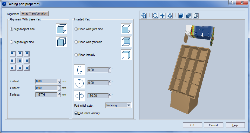
Alignment with Base Part Settings that determine the positioning of the inserted part in respect to the reference one.
Align to front side Sets the front side of the reference part as a target object for the inserted part to stick to.
Align to rear side Sets the rear side of the reference part as a target object for the inserted part to stick to.
Navigation buttons Use the buttons to position the inserted part inside the reference one.
X offset Sets the x-axis offset of the inserted part bearing the reference part.
Y offset Sets the y-axis offset of the inserted part bearing the reference part.
Z offset Sets the offset of the inserted part bearing the target object (defined, using the described above two options) of the reference part.
Inserted Part Settings that determine the positioning of the inserted part. TIP: Play around with the three options that follow to get a meaningful idea of how each one affects the assembly.
Place with front side Sets the front side of the inserted part to be stuck to the corresponding object (defined using the Align to Rear Side) of the reference part.
Place with rear side Sets the rear side of the inserted part to be stuck to the corresponding object (defined using the Align to Rear Side) of the reference part.
Place laterally Places the inserted part on the side of the base part. The options are: (1) Rotate around inserted part's x-axis, (2) Rotate around inserted part's z-axis, and (3) Rotate around base part's z-axis.
Rotation Sets the angle of rotation for the part to be inserted. Value range: [0–360 degrees] or, in radians, [0.00, 5.75].
Part initial state Sets the state in which the currently inserted part will be recognized in the combined 3D presentation.
NOTE: The states that are available depend on the number of originally predefined phases during the design of the inserted part.
Part initial visibility When the check box is selected (the default state) the part is visible in the 3D work area.
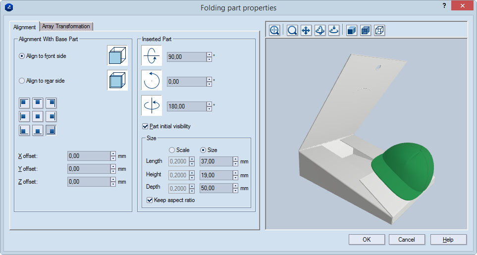
Alignment with Base Part Settings that determine the positioning of the inserted part in respect to the reference one.
Align to front side Sets the front side of the reference part as a target object for the inserted part to stick to.
Align to rear side Sets the rear side of the reference part as a target object for the inserted part to stick to.
Navigation buttons Use the buttons to position the inserted part inside the reference one.
X offset Sets the x-axis offset of the inserted part bearing the reference part.
Y offset Sets the y-axis offset of the inserted part bearing the reference part.
Z offset Sets the offset of the inserted part bearing the target object (defined, using the described above two options) of the reference part.
Inserted Part Settings that determine the positioning of the inserted part. TIP: Play around with the three options that follow to get a meaningful idea of how each one affects the assembly.
Rotation Sets the angle of rotation for the part to be inserted. Value range: [0–360 degrees] or, in radians, [0.00, 5.75].
Part initial visibility When the check box is selected (the default state), the part is visible when you place it into the folding sequence for the first time. If, for construction purposes, you need the part but do not want to see it, leave the check box empty. You can make the part visible at a later stage.
Size Settings for scaling the external object in order to make it fit the structure.
Scale Lets you enter scaling factors by which Prinect will scale the actual values for length, height and depth. If Keep aspect ratio is selected, only Length is enabled.
Size Lets you enter specific values for Length, Height and Depth.
Keep aspect ratio (Applies when Scale is selected.) When the check box is selected, only Length is enabled. Entering a value in it applies also to Height and Depth. Clear the check box to start entering values for all three dimensions.
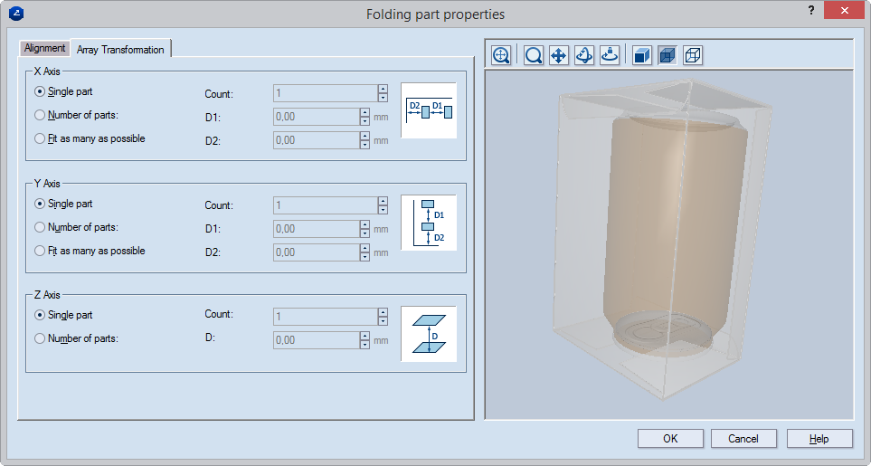
X Axis Settings for the positioning along the x-axis
Single part Displays only one inserted object along the x-axis.
Number of parts Sets the number of inserted parts along the x-axis at the time of the array transformation.
Fit as many as possible Along the x-axis, fits as many inserted parts as possible at the time of the array transformation.
Count (Available when Number of parts is selected) Sets the number of parts along the x-axis.
D1 Along the x-axis, sets the distance between the objects at the time of the array transformation. (Available when either the Number of parts or the Fit as many as possible options is selected.)
D2 Along the x-axis, sets the distance between the outermost objects in the array and the inner sides of the part that the array fits into. (Available only for the Fit as many as possible option.)
Y Axis Settings for the positioning along the y-axis
Single part Displays only one inserted object along the y-axis.
Number of parts Sets the exact number of inserted parts along the y-axis at the time of the array transformation.
Fit as many as possible Along the y-axis, fits as many inserted parts as possible at the time of the array transformation.
Count (Available when Number of parts is selected) Sets the number of parts along the y-axis.
D1 Along the y-axis, sets the distance between the objects at the time of the array transformation. (Available when either the Number of parts or the Fit as many as possible options is selected.)
D2 Along the y-axis, sets the distance between the outermost objects in the array and the inner sides of the part that the array fits into. (Available when the Fit as many as possible option is selected.)
Z Axis Settings for the positioning along the z-axis
Single part Displays only one inserted object along the z-axis. (Count and D are unavailable and display 1 and 0.00, respectively.)
Number of parts Sets the number of inserted parts along the z-axis at the time of the array transformation.
Count (Available when Number of parts is selected) Sets the number of parts along the z-axis.
D (Available when Number of parts is selected) Along the z-axis, sets the distance between the objects at the time of the array transformation.
The Material Properties dialog box appears.
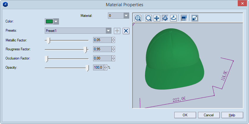
Color Sets the color in which the inserted object will appear.
Material (applies for multi-material 3D models) When working with external objects that consist of more than one material, you can select the exact material whose visual properties you want to set. External objects normally come with various types and number of materials. That is why the program does not identify them by names but by numbers. From the drop-down list, select a number until the material whose visual properties you want to edit is highlighted in the preview area. Then proceed with setting the visual properties as you need them.
Presets A list of presets for the appearance of the inserted object.
Plus sign Adds
a new preset to the list. TIP: Make sure you set the visual properties
of a material BEFORE clicking the Plus sign. After you have set the properties
values, click the Plus sign, and then type a name for the preset.
Remove sign  Removes the selected preset.
Reflection intensity
Diffusive Sets the color and the intensity with which the material diffuses direct light.
Specular Sets the color of the reflected light and the glossiness of the surface.
Ambient Sets the color and the amount of ambient light.
Reflectivity Sets the amount of reflected light on the surface. Moving the slider from 0% to 100% increases the degree of glossiness.
Opacity Sets how much light is transmitted through the surface. 0% means full transparency; 100% means nontransparency.
Preview area
 Zoom Starts the zooming mode for the preview
area.
Zoom Starts the zooming mode for the preview
area.
 Fit Makes the surface sample in the preview
area fit the size of the area.
Fit Makes the surface sample in the preview
area fit the size of the area.
 Pan Starts a mode in which you can move the surface sample across
the preview area.
Pan Starts a mode in which you can move the surface sample across
the preview area.
 Turn Starts a mode in which you can rotate
the surface sample.
Turn Starts a mode in which you can rotate
the surface sample.
 Single Axis Rotation Starts the mode
in which you can rotate the 3D model along a single axis, the direction
being defined by the movement of the mouse.
Single Axis Rotation Starts the mode
in which you can rotate the 3D model along a single axis, the direction
being defined by the movement of the mouse.
 Dimensions Displays the overall dimensions
of the inserted object.
Dimensions Displays the overall dimensions
of the inserted object.
 Scale Object Opens a dialog box in which you can scale an external
object to make it fit the space into which you will insert it.
Scale Object Opens a dialog box in which you can scale an external
object to make it fit the space into which you will insert it.