NOTE: To see the tabular area if it is hidden, on the View menu, click Show tables.
The Create Filter dialog box appears.
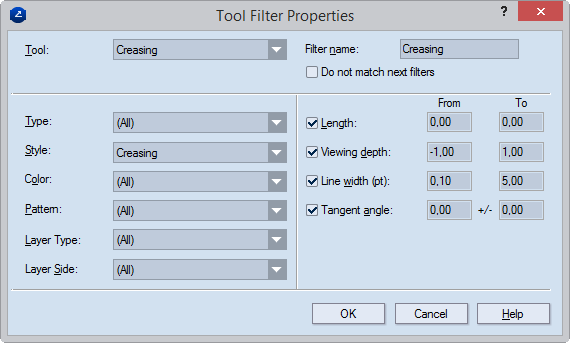
Tool Sets the CAM tool with which the tool filter will associate all objects that have the attributes set for the filter. The list contains all the CAM tools available in the currently loaded CAM template.
Filter name The name of the tool filter. You can edit the name later directly in the Name column of the ToolFilters tab in the tabular area.
Do not match next filters Stops searching through the settings of other filters after a match has been found.
Type Sets the type of tool-filtered objects - point, line, arc, Bézier curve, and so on: all objects of the specified type (in combination with all other attributes) will be associated with the selected CAM tool.
Style Sets the style of tool-filtered objects: all objects with the specified style (together with all other attributes) will be associated with the selected CAM tool.
Color Sets the color of tool-filtered objects: all objects with the specified color (together with all other attributes) will be associated with the selected CAM tool.
Pattern Sets the pattern of the constructional lines or curves of tool-filtered objects: all objects with the specified color (together with all other attributes) will be associated with the selected CAM tool.
Layer Type Select the layer type — Structural Design, Varnishing, Auxiliary or other — to which you want EngView to make selections. NOTE: You can select either one or all layer types.
Layer Side Select the layer side (front or rear) on which you want EngView to select objects. NOTE: You can select either one or all layer sides.
Length Sets the length range of the constructional lines or curves of tool-filtered objects: all objects falling into the specified length range (together with all other attributes) will be associated with the selected CAM tool.
Viewing depth Sets the stack order of a style. Value range: [–1 to 1]. If multiple objects in different styles overlap, the object in the style with the greatest stack order is visible on the screen and the others are not visible regardless of when each object was drawn. Example: If the Cutting style has a stack order of 0.5 and the Axis style has a stack order of -0.4, when objects in the two styles overlap, the one in the Cutting style will always be visible and that in the Axis style will always be not visible.
Line width Sets the line width range of the constructional lines or curves of tool-filtered objects: all objects that fall into the specified line width range (together with all other attributes) will be associated with the selected CAM tool.
Tangent angle Sets the tangent angle range of the constructional curves of tool-filtered objects: all objects that fall into the specified angle range (together with all other attributes) will be associated with the selected CAM tool.