 to set a
different style for tool viewing. NOTE: Style Default means that no style
is selected. Use it if you want to set only a color to a certain object
type, without associating it with a specific style.
to set a
different style for tool viewing. NOTE: Style Default means that no style
is selected. Use it if you want to set only a color to a certain object
type, without associating it with a specific style.When a tool is processing a contour, portions of the material are lost due to the pressure the tool applies to the material. To prevent losing material mass, you can define a material side, a process in which you specify which side of the item being processed will be treated as foremost. This results in positioning the tool in a way that protects the integrity of the material and pressure is applied to the nonessential part of the sheet.
To define material side
The Tool Properties dialog box appears.
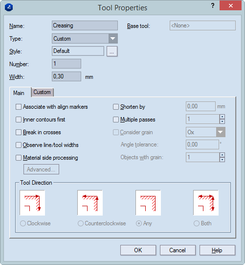
Base tool Available only for child tools. Displays the name of the tool.
Type Sets a type for the tool. Preset types include Router, Laser beam, Water jet, Cutting knife, Creasing wheel, V-cut, Matt cut, and Pen. "Custom" lets you set a new type.
Name Sets the name of the new tool.
Style Displays the style that will be
used to display all the objects processed with the new CAM tool in the
tool path. Click the browse button to set a
different style for tool viewing. NOTE: Style Default means that no style
is selected. Use it if you want to set only a color to a certain object
type, without associating it with a specific style.
Number Sets the number of the new tool as corresponding to the consecutive numbers of the tools on the actual machine. You can change the tool number when you generate the NC file directly. For details, see Generating NC files.
Width Sets the width of the tool as corresponding to the tool width on the actual machine.
The Main tab
Associate with align markers Associates the current tool with align markers.
Inner contours first Generates a tool path in which the current CAM tool starts processing the inner objects first. For example, you make a CAM sample of a packaging box with an inscribed ellipse on one of the sides, cutting the outer contours first will leave the cutting of the ellipse for the last of the use of the cutting tool. As a result, the sheet will not hold so steadily on the samplemaking machine.
Material side processing Sets properties for processing of the material. These include the side on which the cutting will be done, the lead-in and lead out settings, and the directions of processing for the inner and outer sides. To edit the settings, click Advanced, and then in the dialog box that appears edit the settings.
Observe line/width tool widths Takes into account the difference in width between a tool whose width is smaller than the width of the object to be processed, and makes additional runs of the tool so that the necessary width is processed. For example, if the object is 6 points wide and the tool's width is 2 points, the width of the resulting object will be less than the 6 points needed. In this case, the tool will make additional runs to process the needed 6-point width.
Shorten by Shortens the creasing objects by a certain distance, so that the creasing wheel stops before the end of the creasing lines. This prevents the damage in the 1up to creasing regions which are adjacent to the creasing lines. In the edit box on the right-hand side, enter the distance, in the current metric units, by which you want to shorten the creasing objects.
Multiple passes Performs multiple creasing on objects. Enter a number of passing of the creasing tool. Allowed value range: [0, 3]. This is very useful in some cases when the material is tougher - the creasing objects must be processed a couple of times, so that they are easier to fold later.
Consider grain Defines if the grain direction is along the Ox or Oy coordinate axis, depending on the sheet placement.
Angle tolerance Defines the maximal angle by which the creasing tool should be allowed to veer off from the Ox/Oy grain direction, respectively.
Objects with grain Sets a special number of creases for the objects processed with grain direction. Usually this number will be smaller than the number in the Multiple crease check box. Thus you can make a difference (in terms of multiple creases) between the creasing objects processed with grain and the ones processed against grain. Value range: [0, 3].
The Custom tab
Name Displays the name of the property. Check the custom properties that you want the child tool to inherit from the parent primary tool.
Value Sets the default value of the property.
Units Sets the default units.
Visible Indicates if the tool will be visible.
Comment Displays comments on the setting.
Tool Direction
Clockwise Processes the outside contour clockwise.
Counterclockwise Processes the outside contour counterclockwise.
Any The processing direction — clockwise or counterclockwise — is chosen at random.
Both Processes the contour both clockwise and counterclockwise.
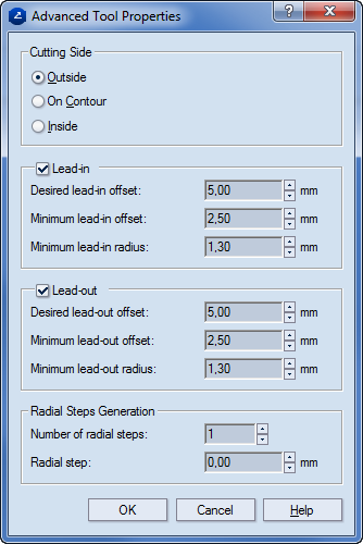
Cutting Side Specifies the zone where the cutting tool will go.
Outside The cutting is done on the outside of the contour, eating into the waste.
On contour The cutting is done along the contour.
Inside The cutting is done on the inside of the contour, eating into the material.
Lead-in
Minimum lead-in offset Sets the lowest applicable lead-in offset.
Desired lead-in offset Sets the lead-in offset that you want to have.
Minimum lead-in radius Sets the lowest applicable lead-in radius.
Lead-out
Minimum lead-out offset Sets the lowest applicable lead-out offset.
Desired lead-out offset Sets the lead-out offset that you want to have.
Minimum lead-out radius Sets the lowest applicable lead-out radius.
Radial Step Generation (Unavailable when "On contour" is selected in the Cutting Side area) Settings about the movement of the tool when the integrity of the material must be taken into account. That is, when the material must be processed in a way that guarantees that the cutting line contour indicates the actual outer edge of the material after the processing has finished.
Number of radial steps Sets how many times the tool will pass along the contour to effect the processing of the material. Depending on the option selected in the Cutting Side area, this can be either outside the contour or inside it.
Radial step Sets the distance at which each next passage of the tool will differ from the preceding one. NOTE: Applies for the steps after the first one — that is, if there will be only one radial step, the value in Radial step will necessarily be zero (0).
 .
.
Material and waste sides defined for areas around a cutting tool. The hatch indicates the material side.
A contextual edit bar appears above the graphical area.
 .
.NOTE: When you have started material side definition, the default material side is applied. You can either: (1) change it automatically, or (2) keep it and then use manual material side definition by applying the By Objects functionality.
The Select Material Side dialog box appears.
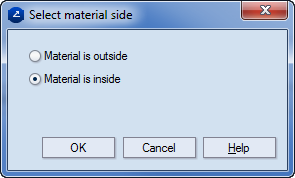
NOTE: Inside and outside refer to the sides around a contour: the area that a contour encloses is referred to as inside, the area beyond the contour, as outside.
 , and
then in the graphical area use the mouse to set material side along
the contour, on the places where you want.
, and
then in the graphical area use the mouse to set material side along
the contour, on the places where you want.