In this video presentation we generate sample
counter channels for all creasing lines in a 1up design. Then we will
make a CAM sample by generating the tool path of the sample counters and
of the 1up design.
Video: Generation of sample counter channels
for creasing lines
Click the icon to watch the video. Run time: 1:51 min.
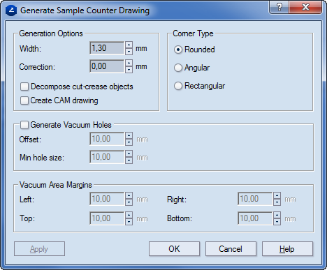
To make the channel side lines meet at a right
angle, under Corner Type,
click Angular.
Under Generation
Options, in Width, enter 3.00
mm. (The distance between the channel's side lines.)
In Correction,
enter 4.00 mm. (This is the distance between the end of the creasing
line and the ends of the channel side lines as projected on the creasing
line.)
notes
The correction
makes the creasing tool stop before the end of the creasing line.
This prevents the creasing of the adjacent regions.
Ensure that
the Correction value is not smaller
than the Width value. This prevents
two or more creasing lines that meet at an acute angle from ending
up overlapping the sample counter's channels.
In both Offset and Min
hole size, enter 35.00 mm and 30 mm, respectively.
Under Vacuum Area Margins, in both
Left and Right,
enter 15 mm.
Click OK.
(Optional)
To hide the 1up (parent) drawing, in the graphical area, right-click
anywhere, and then clear Show drawing
on the context menu.
On the Objects tab, click Rectangle, and then in the
right-hand counterplate section, draw two rectangles in the Counterplate
style (see video).
On the CAM toolbar, click New
CAM,
and then click Generate Tool Path.
 .
. .
.

 , and then in the
right-hand counterplate section, draw two rectangles in the Counterplate
style (see video).
, and then in the
right-hand counterplate section, draw two rectangles in the Counterplate
style (see video). .
. .
.