A layout serves as the basis on which the dieboard design begins. When a layout is being created for a die, the sheet that will be used and the layout array must match the diecutting machine's work area.
NOTE: The example that follows uses the EVF11001 Reverse Regular Tuck Lock resizable design. (The design is located in \\EngViewWork7\Standards Library\mm\Standards\Folding Carton\EngView\EVF1 Glued Boxes\EVF11 Rectangular\EVF110 Tuck Lock – Tuck Lock.)
The example begins from a layout already created.
A layout drawing of the EVF11001 Reverse Regular Tuck Lock resizable design, according to the 1X1 layout pattern
Video: Designing dieboards
![]() Click the icon to watch the video. Runtime: 2:53 min.
Click the icon to watch the video. Runtime: 2:53 min.
The following steps concern the design of a dieboard — from the selection of a dieboard up to the placement of the bridges.
Selecting a dieboard
 .
.The Object Properties dialog box appears.
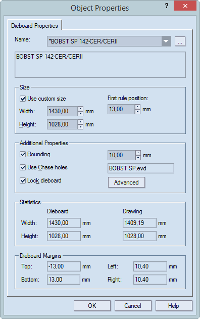
Name Displays
the name of the dieboard. To choose a different dieboard, click the dropdown
list, and then in it select a dieboard. To add a dieboard to the list,
click the browse button  , and
in the dialog box that appears, choose a dieboard. For help about how
to manage the dieboards that appear in the dropdown list, see Managing
dieboards.
, and
in the dialog box that appears, choose a dieboard. For help about how
to manage the dieboards that appear in the dropdown list, see Managing
dieboards.
Size Sets custom dimensions of the dieboard and the position of the first rule (the distance between the lower edge of the dieboard and the first rule).
By default, the properties in the Size area are unavailable for editing. If any changes need to be made to the dieboard size, click the Use custom size check box to make the properties editable. NOTE: Any changes made to the width, length or first rule position apply only to the dieboard for the current project, not to the predefined board as it is stored in the database. Learn more about how to edit a predefined dieboards.
Additional properties Sets the rounding of the dieboard corners, the use of chase holes, the locking device and the centerline properties.
Rounding Sets the rounding of the dieboard corners. In the box, the rounding radius value is entered.
Use chase holes Enables the use of chase holes. The box opposite displays the name of the current chase holes template.
Lock dieboard Fixes the size of the dieboard. This means that, for example, when stripping knives are set, the length and width of the dieboard does not change and will always fit the diecutting machine's work area.
Advanced Opens a dialog box in which the properties of the centerline are set. Learn how to edit a centerline.
Statistics, Dieboard Margins (read-only) Displays the current settings of the dieboard and of the layout drawing. Negative values for the drawing mean that the layout's dimensions are greater than those of the dieboard. This necessitates either alterations to the layout or selection of a new dieboard.
NOTE: The selected dieboard displays the chase holes that are selected by default. You can use them or add additional ones. You can positioning the chase holes manually and/or automatically. In the example, automatic arrangement will be used.
Editing the chase holes
 ..
..
 .
.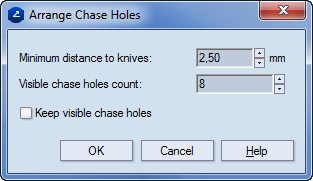
Set a minimal distance to the knives and a number for the active chase holes.
To keep the chase holes that have appeared by default (see the image in Step 3), select the Keep visible chase holes check box.
Click OK.
NOTE: In this step the selection of chase holes is done automatically. You can use both automatic and manual selection of chase holes.
Placing stripping rules
 ..
..A contextual edit bar appears above the graphical area.

 Mirror stripping knife Positions an identical
stripping knife at the opposite end of the dieboard.
Mirror stripping knife Positions an identical
stripping knife at the opposite end of the dieboard.
 Horizontal stripping knife Positions a
horizontal stripping knife.
Horizontal stripping knife Positions a
horizontal stripping knife.
 Vertical stripping knife Positions a vertical
stripping knife.
Vertical stripping knife Positions a vertical
stripping knife.
 Bottom left stripping knife Positions
an L-shaped stripping knife.
Bottom left stripping knife Positions
an L-shaped stripping knife.
 Bottom right stripping knife Positions
a vertically mirrored L-shaped stripping knife.
Bottom right stripping knife Positions
a vertically mirrored L-shaped stripping knife.
 Top right stripping knife Positions an
L-shaped stripping knife mirrored both horizontally and vertically.
Top right stripping knife Positions an
L-shaped stripping knife mirrored both horizontally and vertically.
 Top left stripping knife Positions a horizontally
mirrored L-shaped stripping knife.
Top left stripping knife Positions a horizontally
mirrored L-shaped stripping knife.
D1  The length of the stripping rule's end.
D2  The length of the stripping rule's length outside of
the sheet.
The length of the stripping rule's length outside of
the sheet.
X Offs The horizontal offset of a stripping rule, measured from the current position of the mouse pointer.
Y Offs The vertical offset of a stripping rule, measured from the current position of the mouse pointer.
NOTE: The following image is an example. In your project, position the stripping rules in whatever places you need.

NOTE: To strip angular areas and areas whose shape requires precise stripping, use L-shaped stripping knives. They ensure that the waste to be stripped properly in areas that are difficult to access.
L-shaped stripping knives positioned so as to enable the precise stripping of hard-to-reach places
Placing compensating rules
 ..
..NOTE: The Compensating
Rules button
is unavailable when the selected dieboard is with automatic margins and
is unlocked. To use the functionality, lock the dieboard (right-click
the dieboard's contour, and then click Lock.)
The Compensating Rules dialog box appears.
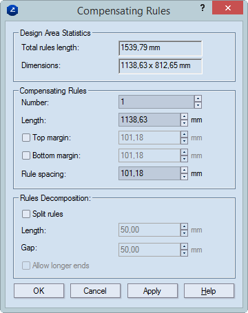
Design Area Statistics This group shows information about the length of the used rules and the overall dimensions as defined by the rules' end points.
Total rules length Shows the total length of the rules — cutting and creasing — in the drawing.
Dimensions Shows the distance between the outermost points of the rules in the drawing (measured horizontally and vertically).
Compensating Rules Governs the spatial positioning of the rules on the dieboard
Number Sets how many compensating rules will be placed on the dieboard. On the dieboard, they are positioned horizontally and one below the other. They occupy the horizontal rule-to-rule length.
Length Sets the length of the compensating rules.
Top margin Sets the distance between the uppermost rule and the dieboard's top edge.
Bottom margin Sets the distance between the bottommost rule and the topmost cutting rule.
Rule spacing Sets the vertical distance between the rules.
NOTE: The Top margin, Bottom margin and Rule spacing properties are interdependent. At any time, one of the them is unavailable for editing. You can choose whether to set the top and bottom margins, or a combination between one of them and the rule spacing — the third dependent property is then computed automatically.
Rules Decomposition Defines the division of a compensating rules into a number of smaller pieces.
Length Defines the length of the rule pieces.
Gap Defines the gap between the rule pieces.
Allow longer ends When the values entered in Length and Gap result in the rule's ends' being short of complete segments, Package Designer recomputes the division to make the end segments of greater length than the one set, respectively, in Length and Gap. NOTE: The division of the rule into pieces begins always from the rule's center.
A dieboard with one compensating split rule
Placing bridges
 .
.The Bridges Drawing View Side dialog box appears.
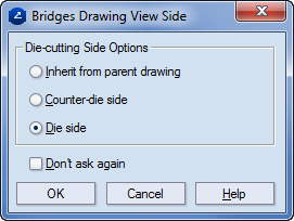
Die-cutting Side Options Selects the side from which the bridges drawing will be viewed.
Inherit from parent drawing Creates the bridges drawing to be viewed from the same side as the design drawing.
Counter-die side Creates the bridges drawing to be viewed from the printed side, irrespective of the view of the parent design drawing.
Die side Creates the bridges drawing to be viewed from the die side, irrespective of the view of the parent design drawing.
Don't ask again Skips the appearance of the dialog box in future work. NOTE: To invoke the message box again in the future, on the Tools menu, click Options, and then in the Questions in prompts tab, select the check box in the corresponding row. Learn how to manage suppressed messages.
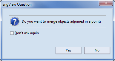
A message appears asking you if you want to merge the sjame-style objects which are adjoined in a point.
A Bridges drawing appears, in which you can manage the bridges on the dieboard.
 .
.The Place Bridges dialog box appears.
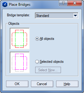
In Bridge template, select a template.
To place bridges on all the objects in the drawing, in the Objects area, click All Objects.
In the Bridges drawing, the bridges appear as empty segments along the rules. NOTE: Bridges are editable objects — both their positions and lengths can be edited as suits the case.
As a next step, proceed with cutting the dieboard.