基本レイアウト自動修復
For the successful automatic layout recovery of an imported file, it
is critical that the outer contour —
the continuous contour formed by the outer objects of the original layout
drawing — is both
closed (that is, there are no gaps in it) and in the Cutting style.
When imported into Package & Display Designer, files from external
formats keep their own styles and their outer contours often have gaps,
which makes the recovery impossible. That is why, once you have imported
a file, it is necessary to:
- Apply the Cutting style to the objects that
make up the outer contour. To do this, right-click an object from
the outer contour, point to Select,
and then click By color. This selects
all the objects that are in this color. When the objects are selected,
apply the Cutting
style to them. TIP: If all the lines in your drawing are in the
same style, select by hand the objects that you want to form the outer
contour, and then apply the Cutting style to them.
- Check if the outer contour is closed — that is, that there are no gaps
in it. TIP: This is best done by using the Fill
functionality. (1) Draw a closed contour around the drawing. (The
easiest way is to draw
a rectangle —
this guarantees that the contour will be closed). (2) Use the Fill
functionality and click anywhere in the area between the drawn rectangle
and the original drawing. (3) Inspect if the fill enters the original
drawing: if the fill surrounds the original drawing without getting
in the drawing, then the outer contour of the original drawing is
closed. The following picture displays the method.
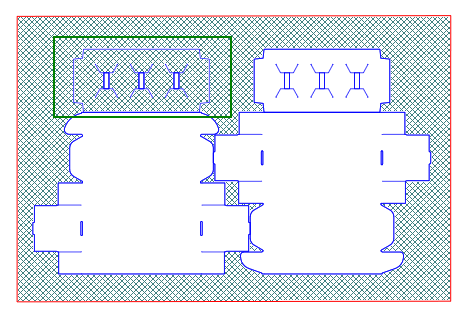
Closed contour as defined by drawing a rectangle
around the original layout drawing. The fill applied to the drawn rectangle
shows that the outer contour of the original drawing is closed.
The fill in the upper section of the left-hand
1up (highlighted) shows that there are gaps in this section. This means
that its contour needs to be repaired.
自動修復の使用
- [レイアウトウィザードの実行]チェックボックスにチェックを付けない状態で[OK]をクリックします。
空のレイアウト図面が表示されます。
- 以下の操作のいずれかを実行します。
- レイアウトツールバーで[ 基本レイアウトの復元
]
 をクリックします。
- [ レイアウト
]メニューで[ 基本レイアウトの復元 ]をクリックします。
基本レイアウト自動修復
ウィザードが、 基本 レイアウトページを表示します。
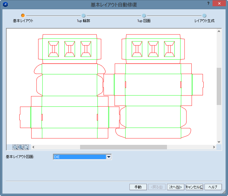
- プロジェクトに複数の図面がある場合は、[基本レイアウト図面]ドロップダウンリストから作業する図面を選択して[次へ]をクリックします。
注: その結果、レイアウト図面の背景に基本レイアウトが薄いグレーで表示されます。
これは、最終的なレイアウト配置を行う際に参照図面として保存できます。 参照図面を削除するには、グラフィック領域のどこかを右クリックし、次にコンテキストメニューの[基本レイヤークリア]をクリックします。
基本レイアウト自動修復
ウィザードが、 1Up 輪郭 ページを表示します。
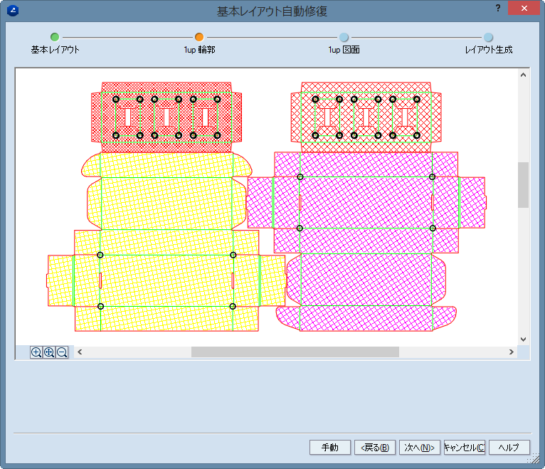
- レイアウト 1up として使用しない輪郭線をクリックしてから、[次へ]をクリックします。
注: 閉じた輪郭線はすべて初期状態ではタイプ別に異なる色でハッチ処理されています。
輪郭線をクリックするとハッチが除去され、輪郭線が後からレイアウト 1up として処理されることがなくなります。
基本レイアウト自動修復
ウィザードが、 1Up 図面 ページを表示します。
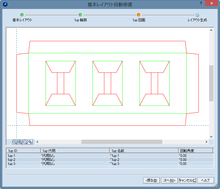
- (オプション)別の図面を 1up として使用する場合は、現在の図面の代わりに使用する図面を[1Up 代用]カラムで選択します。 図面がレイアウトに表示されないようにするには、[無視]を選択します。
- (オプション)[1up 名前]カラムで
1up の名前を編集します。
- (オプション)[回転]カラムで
1up を 0 度、90 度、180 度、270 度のいずれかに回転させます。
- [次へ]をクリックします。
基本レイアウト自動修復
ウィザードが、 レイアウト生成
ページを表示します。
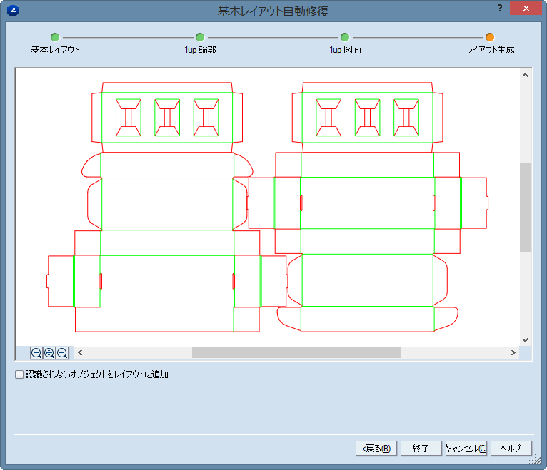
- (オプション)1up 以外のレイアウトにオブジェクトを追加する場合は、[認識されないオブジェクトをレイアウトに追加]チェックボックスを選択します。
注: 1up 以外のオブジェクトにはたとえば、テーブル、説明、ストリップナイフ、マーカーなどがあります。