 .
.You can generate counters for creasing lines. The counters are channels cut in the place of the creasing lines cut out in the same material as the sample. Once this is done, another sheet of the material is placed on top of the counter sheet to cut the actual sample. When the creasing wheel goes over the creasing lines to produce the sample, it sinks deeper into the pre-cut channels. Thus you get much better formed creases on the sample that are similar to real creases produced by a cutting die and counterplates. Various parameters allow you to set the style of the counter channel endings, width and offset corrections.

IMPORTANT: To create sample counters, you must have creasing lines in your 1up.
To create sample counters
.A drawing with a name [Drawingname] ToolPath appears, where Drawingname is the name of the project's open 1up, layout or counterplate drawing.
 .
.NOTE: For a 1up you can create any number of counterplate drawings.
The Generate Sample Counter Drawing dialog box appears.
Generation Options
Width Sets the width of the channel. This is the distance between the two side lines of the channel. Optimally, the Correction value should not be smaller than the Width value. This prevents creasing lines that meet at an acute angle from overlapping the sample counter's channels.
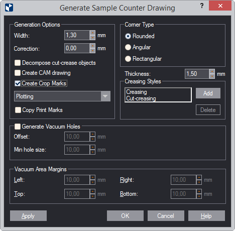
Correction Sets the creasing line correction of channels. This is the distance between the end of the creasing line and the ends of the channel side lines as projected along the creasing line.
The creasing line correction makes the creasing tool stop before the end of the creasing line, thus preventing it from creasing regions adjacent to the creasing lines. Optimally, the Correction value should not be smaller than the Width value. This prevents creasing lines that meet at an acute angle from overlapping the channels of the sample counter.
Decompose CutCrease objects Decomposes all objects in the CutCrease style, or styles based on it, into cutting and noncutting fragments, and makes them discrete objects.
Create CAM drawing Generates the samplecounter along with a CAM drawing.
Create crop marks Creates a crop mark that indicates the bounding rectangle of the tool path. These marks are then used as pinpoints on the machine's coordinate system. In the dropdown list, select a style for the crop mark. For example, in Kongsber machines, (0,0) of the coordinate system is the lower left point of the tool path's bounding rectangle. We use crops marks to accurately identify this point.
Copy print marks Copies print marks in the 1up to the sample counterplate. The print marks are copied in their default styles.
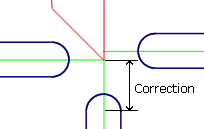
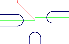
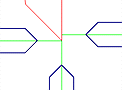
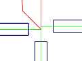
Corner type Determines how channel ends will close.
Uses an arc to round channel ends
Channel side lines meet at an right angle
Uses a straight line to connects channel sides' ends
Thickness Sets the thickness of the material for the sample counter. This value can be written in the NC file and sent to the plotter.
Creasing styles Here, you can specify the objects that you want Prinect to process as creases. Creasing and Cut-Crease styles appear by default. You can add more style by clickig the Add button, and selecting from the list that appears. To remove a style that you do not need, select it in the list, and then click Delete.
Generate Vacuum Holes
Offset Sets the offset of the vacuum holes in relation to the nearest object found — a creasing line, a channel side line, or a vacuum area margin.
Min hole size Sets the minimal size of the vacuum holes to be placed on the samplecounter. All vacuum holes that meet the minimal hole size criterion are generated on the sample counter — that is, the greater the Min hole size value, the fewer the vacuum holes.
Vacuum Area Margins
The controls are available when Generate Vacuum Holes is selected. By entering values for the margins, you set the vacuum area's position with regard to the design's bounding rectangle. When all the margins are set to 0, the vacuum area coincides with the bounding rectangle.
A new drawing with a name [Drawing name] SampleCounter appears, where Drawing name is the name of the starting 1up, layout or counterplate drawing.
Notes