Generating different clip paths (bleed) on either side of a design
The procedure that follows the generation of bleed on both sides
of a design. This is genrally the case when you want to apply artwork
also onto the side that is on the inside of a packaging item.
To generate clip paths (bleeds) on both the
front and rear sides
- On the , click Generate
Bleed by Levels of Importance
 .
.
A contextual edit bar appears above the graphical
area.
Marking areas
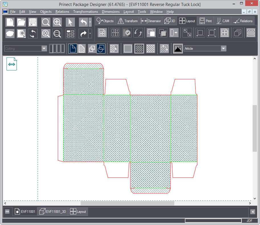
You start by marking out the zones that you want to the bleed to
cover (important) and those that must be free of bleed (unimportant).
- Select the areas on which no artwork will be placed: click
No Artwork
 ,
and then, in the design, consecutively click the areas that will
be free of artwork.
,
and then, in the design, consecutively click the areas that will
be free of artwork.
- Select critical artwork areas: in the contextual edit bar click
Important Area
 ,
and then, in the design, consecutively click the respective areas.
,
and then, in the design, consecutively click the respective areas.
- Select less critical artwork areas: in the contextual edit
bar click Unimportant Area
 , and then, in the design, consecutively click the
respective areas.
, and then, in the design, consecutively click the
respective areas.
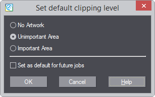
- (Optional) If you want to mark the entire design as the same
type of clipping area, click Set All
Regions
 .
.
The Set Default
Clipping Level dialog box appears, in which you can set a default
clipping area that Prinect
will use in future. (Select the option that you want, and then click
the Set As Default For Future Jobs check box.)
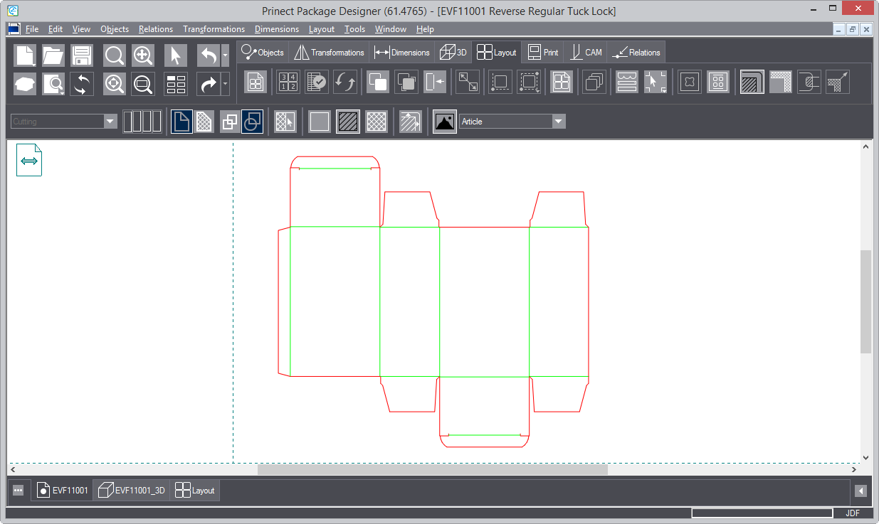
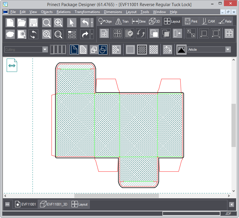
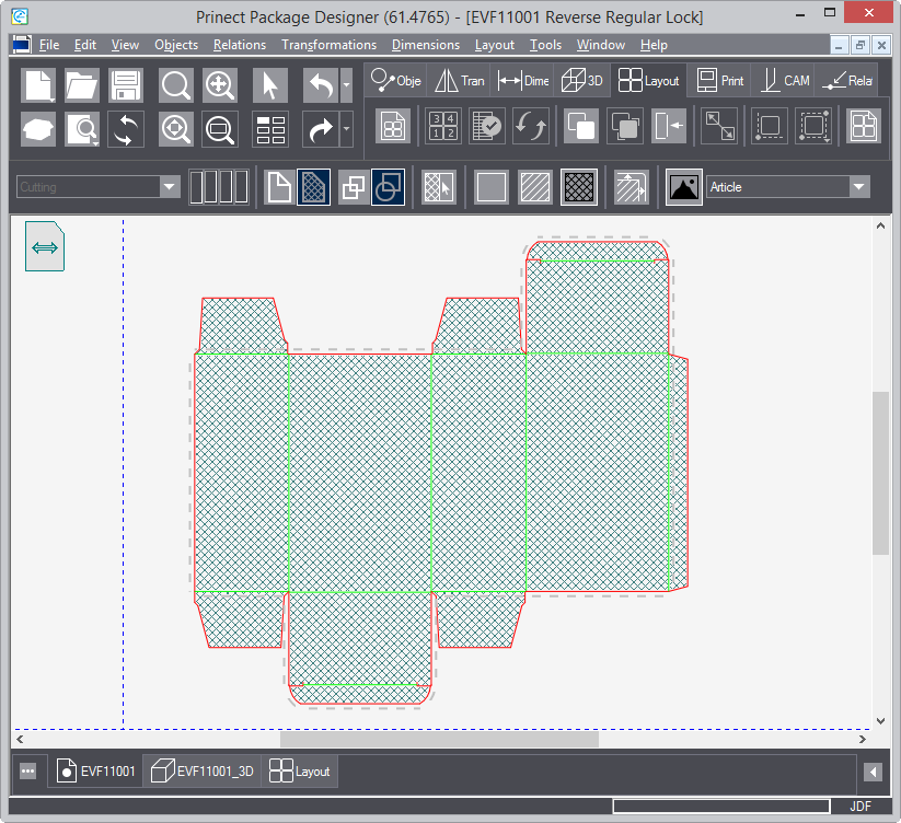
After you have marked out the important and
unimportant areas, the design should look something like this:
Generating the front side bleed
- We then move to generating bled on the design's front side.
First, make sure the Different Front Rear button is pressed in.
- To generate the bleed, click Generate Bleed
 .
.
The Bleed Generations Options dialog box
appears, in which you set the offsets for the bleed.
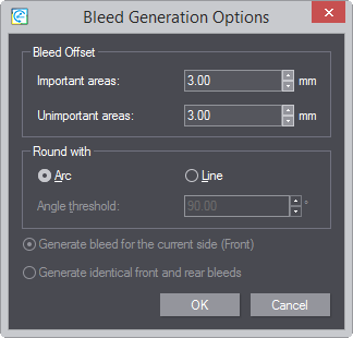
| Bleed Offset |
In this group, we enter values for how far the bleed will
lie off the outer contours of the important and unimportant
areas. NOTE: In the general case, the value for the bleed
along the important areas is greater than that for the bleed
along the unimportant areas. |
| Important areas |
How far away from the outer contours of the important areas
the bleed will lie. |
| Unimportant areas |
How far away from the outer contours of the unimportant
areas the bleed will lie. |
| Round With |
Choose whether to use arcs or lines for the angle roundings
of the bleed. |
| Angle threshold |
Available when the Line option is selected. This is the
greatest value that Prinect
may use when rounding adjacent bleed lines. |
| Generate current side bleed (side) |
Prinect
will apply the set bleed only to the side that is currently
facing you. |
| Generate identical front and rear bleeds |
Prinect
will apply the set bleed values both the facing side and the
reverse sides. |
IMPORTANT: While working, this dialog box
may show various warnings depending on specific situations. Pay attention
to the warnings and take measures accordingly. The warnings alert
to specifics in the generation of bleed.
- To generate the bleed, enter the offset values, and then click
Generate Bleed .
Prinect applies the bleed around the areas
inicated Important.
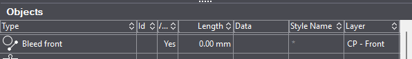
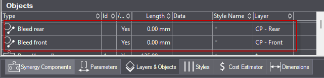
Indicating the applied bleed in the Layers & Objects table
The applied bleed is indicated also in the Layers & Objects
table. Depending on the selected application, you can see different
table entries:
 top of page
Generating the rear side bleed
We now move to generating the bleed on the rear side.
- On the bleed toolbar, click View Back
 .
.
Prinect switches the design and we now view
its rear side.
- When you have marked out the zones to be covered by the bleed,
click Generate Bleed .
The Bleed Generations Options dialog box
appears.

- Enter the bleed offset value for the bleed. They may be the
same as the ones for the front bleed, or different as your case
requires.
- When ready, click OK. Prinect
applies the new bleed.
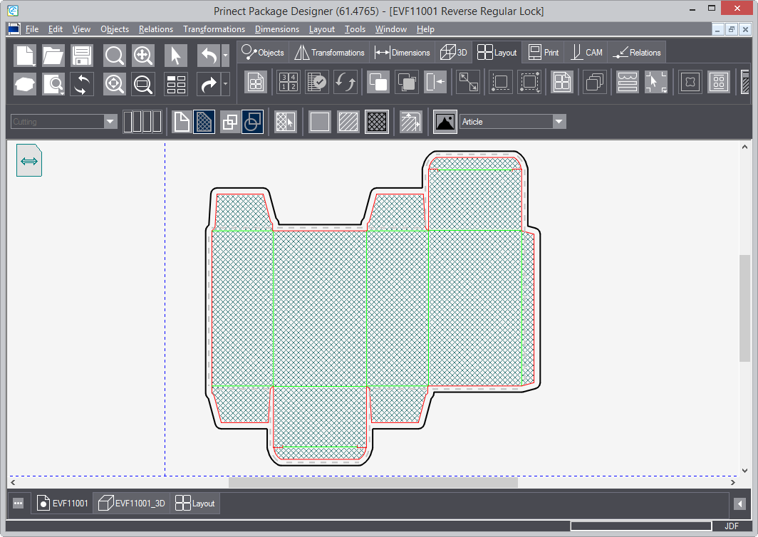
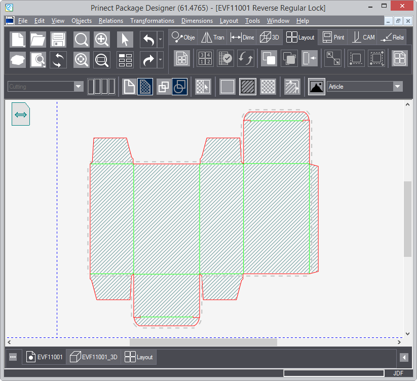
Notice the two bleeds: the front side one is indicated by a dashed
line, while the rear side bleed (facing you) is in black. This is
the case because the bleed values for the front and rear sides are
here different. If you make them identical, the two bleed indicating
lines will overlap producing a single two-color line.
Indicating the applied bleed in the Layers & Objects table
The applied bleed is indicated also in the Layers & Objects
table. we now see the two generated bleeds -- for the front and the
rear sides.
 top of page