Adjusting the position of inserted parts and 3D objects

Once you have inserted an external 3D object, you can begin adjusting its position in the 3D model area. You can also choose how many pieces of the object are to be used in the box and arrange the resultant array.

To adjust the position of an inserted 3D object

  1. Do any of the following:

The Inserted Part Properties dialog box appears for the inserted object.

Aligning the folding parts

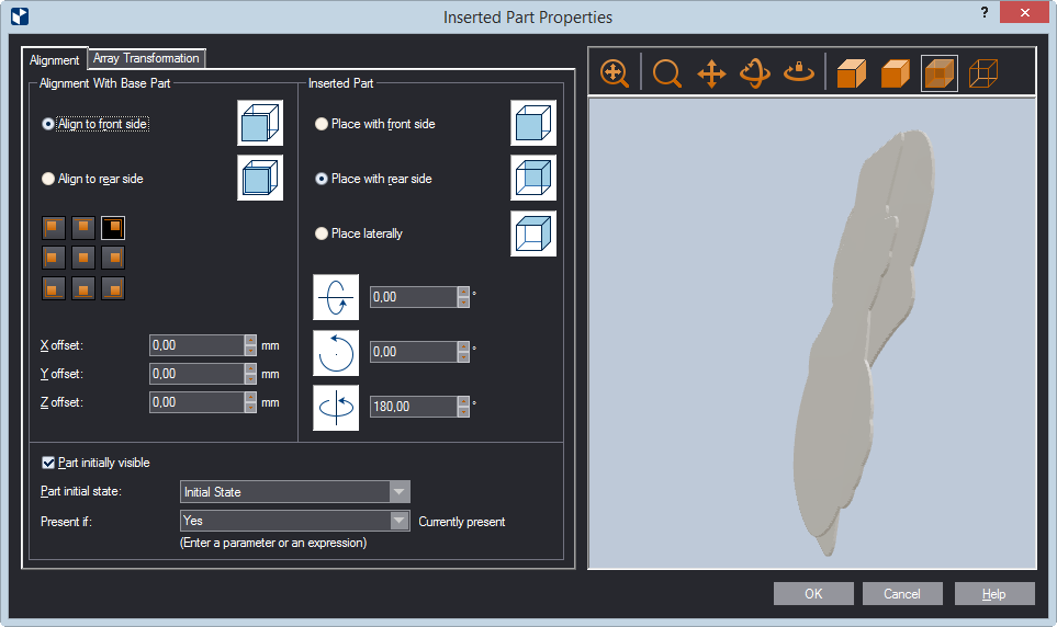
  Alignment with Base Part Settings that determine the positioning of the inserted part in respect to the hosting one.
  Align to front side Sets the front side of the hosting part as a target object for the inserted part to stick to.
  Align to rear side Sets the rear side of the hosting part as a target object for the inserted part to stick to.
  Positioning buttons Use the buttons to position the inserted part in the hosting one.
  X offset Sets the x-axis offset of the inserted part bearing the hosting part.
  Y offset Sets the y-axis offset of the inserted part bearing the hosting part.
  Z offset Sets the offset of the inserted part bearing the target object (defined, using the described above two options) of the hosting part.
 
  Inserted Part Settings that determine the positioning of the inserted part. TIP: Play around with the three options that follow to get a meaningful idea of how each one affects the assembly.
  Place with front side Sets the front side of the inserted part to be stuck to the corresponding object (defined using the Align to Rear Side) of the hosting part.
  Place with rear side Sets the rear side of the inserted part to be stuck to the corresponding object (defined using the Align to Rear Side) of the hosting part.
  Place laterally Places the inserted part on the side of the base part. The options are: (1) Rotate around inserted part's x-axis, (2) Rotate around inserted part's z-axis, and (3) Rotate around base part's z-axis.
  Rotation Sets the angle of rotation for the part to be inserted. Value range: [0–360 degrees] or, in radians, [0.00, 5.75].
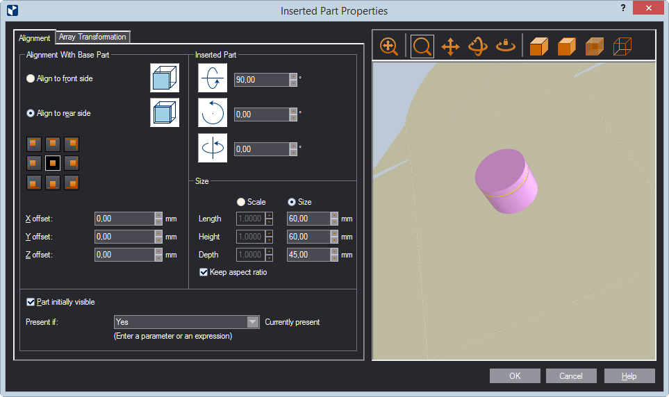
  Size (External object only) Settings for scaling the external object in order to make it fit the structure.
  Scale Lets you enter scaling factors by which EngView will scale the actual values for length, height and depth. If Keep aspect ratio is selected, only Length is enabled.
  Size Lets you enter specific values for Length, Height and Depth.
  Keep aspect ratio (Applies when Scale is selected.) When the check box is selected, only Length is enabled. Entering a value in it applies also to Height and Depth. Clear the check box to start entering values for all three dimensions.
 
  Visibility Settings  
  Part initially visible When the check box is selected (the default state) the part is visible in the 3D model area. Use it to control whether you want the object to be visible at the very start of a folding sequence. Very often it is not what you need.
  Part initial state Set the phase at which you want to view the inserted part when it first appears in the folding sequence.
  Present if You can link the presence of the object in the folding sequence to a parameter or an expression that evaluates to Yes or No. You then type the Yes/No value or expression here. When the thus typed condition is met, the object appears in the folding sequence; when not, it does not appear. Learn more about how to control the presence of objects in folding sequences.
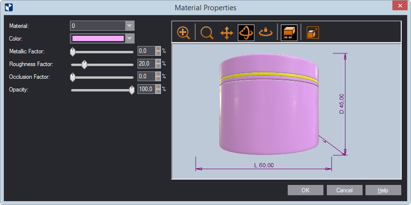
 
Icon Control Name What It Does
Fit Fits the appearance model into the preview area.
Zoom Starts zooming inside the preview area.
Pan Starts moving the appearance model across the preview area.
Turn Starts rotating the appearance model within the preview area.
Single Axis Rotation Starts rotating the appearance model along the axis defined by how you move the mouse.
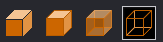
Object Transparency Four options for how transparent you can view the inserted object: Solid, Solid Wired, Wireframe and Transparent
Scale Object (External object only) Opens a dialog box in which you can scale an external object to make it fit the space into which you will insert it.

Setting the spatial position

X Axis Settings for the positioning along the x-axis
Single part Click to use a single inserted object along the x-axis.
Number of parts Set how many inserted parts you want along the x-axis.
Fit as many as possible Fits as many inserted objects as possible along the x-axis.
Count (Available when Number of Parts is selected.) Sets how many external objects will be inserted along the x-axis.
D1 Sets the distance between the inserted parts along the x-axis. (Available when either the Number of Parts or the Fit as Many as Possible options is selected.)
D2 Sets the distance along the x-axis between the outermost objects in the array and the inner sides of the part that the array fits into. (Available only for the Fit as Many as Possible option.)
 
Y Axis Settings for the positioning of inserted objects along the y-axis
Single part Click to use a single inserted object along the y-axis.
Number of parts Set how many inserted parts you want along the y-axis.
Fit as many as possible Fits as many inserted objects as possible along the y-axis.
Count (Available when Number of Parts is selected.) Sets how many external objects will be inserted along the y-axis.
D1 Sets the distance between the inserted parts along the y-axis. (Available when either the Number of Parts or the Fit as Many as Possible options is selected.)
D2 Sets the distance along the y-axis between the outermost objects in the array and the inner sides of the part that the array fits into. (Available only for the Fit as Many as Possible option.)
 
Z Axis Settings for the positioning of inserted parts along the z-axis
Single part Click to use a single inserted object along the z-axis.
Number of parts Set how many inserted parts you want along the z-axis.
Count (Available when Number of Parts is selected) Sets how many parts will be inserted along the z-axis.
D1 Along the z-axis, sets the distance between the objects at the time of the array transformation. (Available when the Number of Parts option is selected.)
  1. Edit the object's properties in a way that works for you.
  2. (STL objects only) To edit the visual appearance of the inserted object, right-click it, and then click Material properties.

The Material Properties dialog box appears.

Material (applies for multi-material 3D models) When working with external objects that consist of more than one material, you can select the exact material whose visual properties you want to set. External objects normally come with various types and number of materials. That is why the program does not identify them by names but by numbers. From the drop-down list, select a number until the material whose visual properties you want to edit is highlighted in the preview area. Then proceed with setting the visual properties as you need them.
Color Sets a color for the object's surface.
Metallic factor Sets how much the surface will reflect the environment and, as a result, how color will be rendered. 0.0 means no reflection and fully visible color; 1.0 means full reflection and nonvisible color.
Roughness factor Sets how the surface will scatter light and, as a result, whether reflection will be blurry or sharp. 0.0 means sharp, mirror-like reflection; 1.0 means blurry reflection.
Occlusion factor Adds shading to crack-pattern surfaces. This adds a real-life look to the surface.
Opacity Sets how much light is transmitted through the surface: 0.0 means full transparency; 1.0 means nontransparency. Transparency affects how colors are rendered: full transparancy makes color non-visible; nontransparancy makes it fully visible.
  1. In the dialog box, set the properties as you need them.