In this video, we present how to handle materials that are larger than the machine's work area. This is useful for both manual feed and a machine with a roller. The entire procedure includes the use of splitters, draw markers, and align markers.
You can align a design to already existing markers or use automatic drawing of markers. Markers are used as starting points: every time you move the material toward the work area, the align markers ensure that the operation is executed without unacceptable offset.
Video: Splitting designs
![]() Click the icon to watch the video. Run time: 1:27 min.
Click the icon to watch the video. Run time: 1:27 min.
PROCEDURAL STEPS
NOTE ON USING A DIFFERENT END POSITION FOR THE TOOL HEAD: If while processing split designs you need to set an end position for the tool's head that is different from the start one, you need to add a custom machine property to your machine. This ensures that when processing is done, the tool head will stop at the place you need, not where its started from. Learn how to set this property.
 .
. .
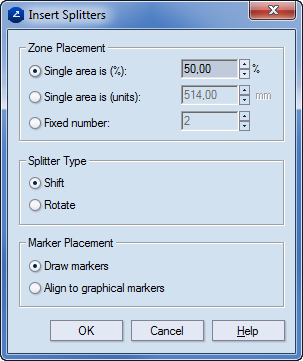
.The Splitter Settings dialog box appears.
notes
Under Zone placement, choose whether to place markers counting the total design by percentage, dividing it into separate areas, or placing a fixed number of markers.
Under Splitter type, use the options to choose whether to shift the design or to rotate it. In some cases it's better to rotate the design rather than split it.
Under Marker placement, use the options to choose whether to draw markers or align to an already existing ones.
 .
. .
. .
.note: To remove the splitters, do any of the following:
.