.
.To begin creating the stripping dies — male and female stripping die and a front stripper — first the contours must be defined which will mark the die areas and, as a result, indicate the waste areas that will be stripped off the dieboard.
NOTE: Prior to defining the die contours, stripping knives need to be placed on the dieboard.
To create die contours
.The Stripping Contour Options dialog box appears.
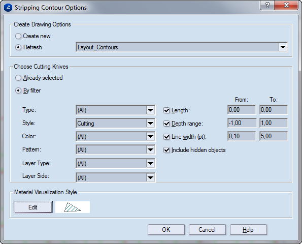
Create Drawing Options In this area you can choose whether to create a new drawing for the stripping contours or use one of those created previously.
Create new Creates a new die contours drawing.
Refresh Updates one of the previously created die contours drawings. (They are accessible in the dropdown list.)
Choose Cutting Knives Sets the cutting knives which will be used for the creation of the die contours.
Already selected The selected drawn objects will serve to define the die contour.
By filter Defines a filter for the objects that determine a die contour. The filter is defined by the following attributes:
Type Selected are objects of the specified type — arc, circle, curve, segment and so on.
Style Selected are objects in the specified style — Cutting, CutCrease and so on.
Color Selected are objects that are in the specified color.
Pattern Selected are objects which are visualized in the specified pattern.
Layer Type Selected are the objects that are present in the specified layer type.
Layer Side Selected are the objects that are present on the specified side of the die.
Length Selects are objects that fall in the specified length interval.
Depth range Selects are objects that fall in the specified depth interval for screen visualization.
Line width (pt) Selects are objects that fall in the specified interval for physical width.
Include hidden objects Also objects that are not displayed on the screen are selected.
Material Visualization Style Sets the hatching pattern that is used to mark the non-waste areas. To change the hatching pattern, click Edit, and then in the dialog box that appears, make changes by hatch (line, cross or pattern), its properties and pattern.
A hatched contour appears in the lower part of the drawing — that's the gutter. This is the first contour, to which will the contour of the packaging pieces will be added to form the overall non-waste contour. There must be only one contour in a drawing.

Notes
 .
.