While working in a bridges drawing, you may find that you need a different type of nicks than the default ones. Note that any locally made changes in the types of bridges or nicks apply only for the currently active drawing. The next time you create a bridges drawing and begin placing nicks, the default bridges and nick settings will apply.
To edit the bridges or nicks in the current bridges drawing
The Bridge drawing properties dialog box appears.
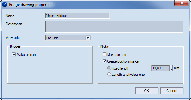
Name Displays the name of the bridges drawing.
Description Displays optional notes about the drawing.
View side Sets on which the side of the drawing — dieside or counterdie side — the knives will be mounted.
Bridges Settings for the positioning of bridges
Make as gap The bridge is visualized as a gap on the screen. In an exported drawing, the gap indicates the place where the hole must be made on the board. If the drawing is sent to a cutting machine, the gap indicates the place where the laser cutter will stop. If the drawing is sent to a rule-bending machine, a hole is placed where the knife is.
Nicks Settings for the positioning of nicks
Make as gap The nick is visualized as a gap on the screen.
NOTE: This functionality is suitable for samplemaking, where the gaps are not cut into the media but are meant to hold the cut design to the sheet. The gaps have the size set in Width (in the contextual edit bar during nicks positioning).
Create position marker (Applies for the preparation of the dieboard) Select the check box when you want to make the nicks by hand. The place where the cutting rule will be cut is engraved on the board.
IMPORTANT: So that the nicks can be seen in the CAM drawing, the Add bridges check box must be selected in the CAM Template Properties dialog box. So that the indications on the board can be engraved, a special filter needs to be created that will control how they are processed. Then choose one of the two options for the length of the notches.
NOTE: While a nick is being placed, its position along the object is measured as percentage from the beginning of the object.
Fixed length Type a length for the how long the nick will be. In the CAM drawing, this length will be sent to the dieboard.
Length to physical size (Applies when the file will be exported. The position marker will reflect the gap's physical size.) When this option is selected, the length of the nick is the same as the length of the position marker.
NOTE: The length of the nick is determined in the currently used template.
IMPORTANT: Bear in mind that if you choose a different nick type, the default screen-length settings for the this nick type will apply. If you will need different values for them, you have to set these values separately.