 to set how the draw marker will appear on the screen. After you have set
the properties, in the read-only field you will see the chosen style name;
in the white field you will see the chosen pattern.
to set how the draw marker will appear on the screen. After you have set
the properties, in the read-only field you will see the chosen style name;
in the white field you will see the chosen pattern.In the procedure that follows you set the default types of bridges and nicks. They will apply next time you begin placing these instruments to a dieboard. At any time during your work you can set local bridges and nicks types that are different from the default ones.
To set default bridges and nicks types
The Bridges and Nicks Options dialog box appears.
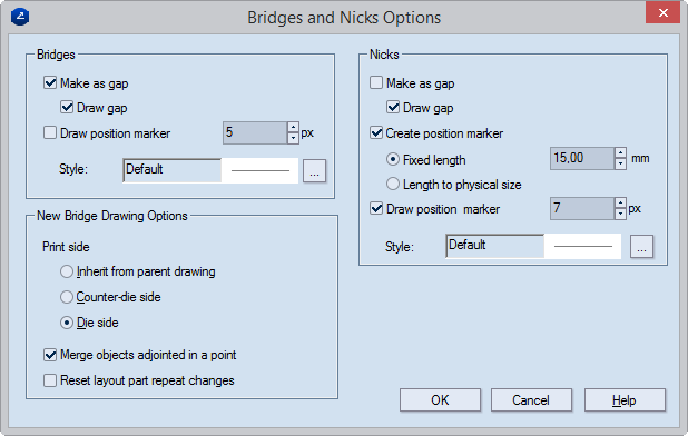
Bridges Default settings for the positioning of bridges
Make as gap The bridge is visualized as a gap on the screen. In an exported drawing, the gap indicates the place where the hole must be made on the board and knives. If the drawing is sent to a cutting machine, the gap indicates the place where the laser cutter will stop. If the drawing is sent to a rule-bending machine, a hole is placed where the bridge is.
Draw gap (Visualization purposes only) On the screen, the object is highlighted in a color (grey by default).
Draw position marker (Visualization purposes only. Size in pixels) A marker is placed where the bridge will be. This marker does not transfer to CAM drawings and does not appear in exported files.
Style The predefined style for the position marker that controls how the position marker appears on the screen. To set a style, click the browse button, and then select a style.
New Bridge Drawing Options Default settings for how to generate bridge drawings
Inherit from parent drawing Creates the bridges drawing to be viewed from the same side as the design drawing.
Counter-die side Creates the bridges drawing to be viewed from the reverse side of the diecutting side.
Die side Creates the bridges drawing to be viewed from the diecutting side.
Merge objects adjoined in a point Conjoins objects in the same style that intersect.
Reset layout part repeat changes Applies to bridge drawings generated from layouts whose parts are rotated differently. When the check box is selected, in the bridge drawing Prinect will apply the Repeat Changes functionality to both groups of layout parts — those at 0 degrees and to the rotated ones.
Nicks Default settings for the positioning of nicks
NOTE: Before adjusting your nick settings, see the various methods for manufacturing of nicks.
Make as gap The nick is visualized as a gap on the screen. The gaps have the size set in Width (viewable in the contextual edit bar during nicks positioning). When exporting as DXF, Prinect exports nicks (1) as gaps if Export Bridges is not selected, (2) as lines if selected. Prinect does not export nicks in the .cff, .dds, and .dde3 file formats.
Draw gap (Visualization purposes only) On the screen, the object is highlighted in a color (blue by default).
Create position marker (Applies for the preparation of dieboard) Select the check box when you want to make the nicks by hand. The place where the cutting rule will be cut is engraved on the board.
IMPORTANT: So that the nicks can be seen in the CAM drawing, the Add bridges check box must be selected in the CAM Template Properties dialog box. So that the indications on the board can be engraved, a special filter needs to be created that will control how they are processed. Then choose one of the two options for the length of the notches.
Fixed length Prinect places the nick as a line perpendicular to the object. Type how long you want the line to be. After exports, nicks are lines with the same length.
Length to physical size When this option is selected, Prinect places the nick as a line perpendicular to the object. Its length is identical with that of the nick's width. After exports, nicks are lines with the corresponding length.
Draw position marker (Visualization purposes only. Size is in pixels) A marker is placed where the nick will be. This marker does not transfer to CAM drawings and will not be carried over during file export.
Style Click the browse button
to set how the draw marker will appear on the screen. After you have set
the properties, in the read-only field you will see the chosen style name;
in the white field you will see the chosen pattern.