
Component Browsing
Image Width Sets the width, in pixels, of parametric components' previews in the upper section of the Synergy Components tab in the tabular area. Value range: 8–256 pixels. NOTE: The size of the lower preview pane in the Synergy Components tab, which displays a preview of the currently selected component, is flexible.
Image Height Sets the height, in pixels, of parametric components' previews in the upper section of the Synergy Components tab in the tabular area. Allowed value range: 8–256 pixels.
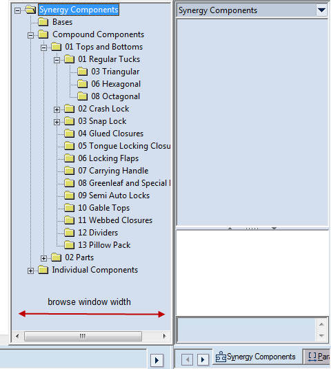
Component Tree width Sets the width (in pixels) of the browse window in which Synergy components are selected. (This is the window that appears when in the tabular area you click the Synergy Components tab, and then click the components list at the top.)
Browse with Libraries' language When this option is selected, you work with the Library of Components in the same language as the Standards Library. NOTE: You set up the language of the Standards Library during the software installation, or later by using the Library Translator tool.
NOTE: This option lets you use different languages for the user interface and the Library of Components — if you change the language of the user interface (in Select Language in the General tab), the Library of Components will remain in the language of the Standards Library.
EXAMPLE: Your installation is in English, which means the Library of Components is in English too. If you switch the software user interface language to German, the Library of Components will remain in English.
Browse with System's language When this option is selected, the Library of Components will be translated automatically in the language that you have chosen for the user interface (in Select Language in the General tab).
IMPORTANT: Currently, each EngView installation offers the Library of Components in English, German and Japanese. To request a translation in a different language, contact support@engview.com.
EXAMPLE: Your installation is in English, which means the Library of Components is in English too. If you switch the software user interface language to German, the Library of Components will be translated into English automatically. If you switch the user interface language to, say, Spanish, the Library of Components will remain in English.
Show
Constraints Displays the constraints of the components you insert in the drawings of all projects you open or create. You can change this behavior for a particular drawing: in the graphical area, right-click, point to Show, and then check or uncheck Constraints as you want it.
Control points Displays the control points of the components you insert in the drawings of all projects you open or create. You can change this behavior for a particular drawing: in the graphical area, right-click, point to Show, and then check or uncheck Control points as you want it.
Hidden objects Displays by default the hidden objects of components you insert in the drawings of all projects you open or create. You can change this behavior for a particular drawing: in the graphical area, right-click, point to Show, and then check or uncheck Hidden objects as you want it.
Dimensions Displays by default the dimensions of components you insert in the drawings of all projects you open or create. You can always change this behavior locally for a particular drawing: in the graphical area, right-click, point to Show, and then check or uncheck Dimensions as you want it.
Show overlapping (individual and compound components only) When the check box is selected, in the graphical area the lines are highlighted to which overlapping flags have been applied.
Advanced parameter matching After a component — compound or individual — has been attached, moves its parameters to the project's list of parameters.
IMPORTANT FOR ATTACHING COMPOUND COMPONENTS: During the attachment of compound components, links the parameters of the compound component to those of the base. The component's original parameters — AX2 and AX3 — adopt both the values of their counterparts in the base and their names. In this way, each time you edit the base, Prinect resizes the compound component taking into account your changes.
NOTE: Selecting and deselecting this check box has an effect
when you are working with non-resizable drawings  .
This type of drawing originates when you start a blank
project, a project from an imported
file, or copy a drawing from a resizable drawing. When you are working
with resizable drawings
.
This type of drawing originates when you start a blank
project, a project from an imported
file, or copy a drawing from a resizable drawing. When you are working
with resizable drawings  , the program applies
the functionality regardless of whether the check box is selected. This
type of drawing originates when you start creating a project from a resizable designs
or an external 3D objects,
or start creating a resizable
template.
, the program applies
the functionality regardless of whether the check box is selected. This
type of drawing originates when you start creating a project from a resizable designs
or an external 3D objects,
or start creating a resizable
template.
Automatic Component Attachment Applies for the attachment of compound components and resizable designs.
When SHIFT' is released Connects all control points of the component you are inserting in one step at the moment you release SHIFT: press and hold down SHIFT, click the first control point where you want to connect a component, then release SHIFT.
When SHIFT is pressed Connects all control points of the component you are inserting in one step at the moment you press SHIFT and click the first (or any successive) control point where you want to connect your component.
Automatic attach activation zone When you insert a parametric component into a 1up drawing, the program connects the control points of the to-be-inserted component with control points of previously inserted components. The functionality sets the distance range, in pixels, for detecting existing control points: when the mouse pointer falls within this range — that is, is at a smaller than or equal distance from an arbitrary control point — while you are dragging the to-be-inserted component, the program detects the control point and snaps the component to it. The smaller the precision value, the closer to the control point you need to point to effect detection.
NOTE: The arrows on the right-hand side of the Width, Height and Precision edit boxes alter the value in the respective edit box by a default step of, respectively, 16.00 metric units for Width and Height, and 1.00 metric unit for Automatic attach activation zone. To change the steps, click the rectangular button next to the arrows, and then, in the dialog box that appears, type a new step.