A multiple-page print presentation is created by adding new pages to an existing print drawing.
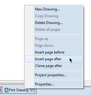
To add a print drawing
NOTE: You can see the number of the new print drawing when you select its design frame — see Step 3.
The Print Frame Placement dialog box appears.
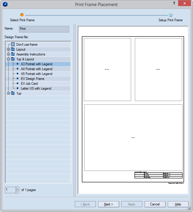
Selecting a design frame for the new print drawing. Note that in the lower left corner of the dialog box, the position of the new print drawing is displayed (dimmed) followed by the total number of pages in the print presentation. The total number of pages includes the page you are creating.
The Print Frame Placement dialog box appears.
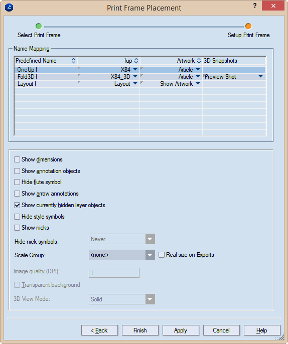
Predefined name Lists the names of all predefined rectangular areas which have been incorporated in the selected design frame.
1up Lists the 1ups and/or layout drawings to be placed in the respective predefined rectangular areas. Each column field is a list. To assign a 1up or a layout to a predefined rectangular area, click in the respective field to open the list, and then select the 1up or layout that you want.
3D Snapshots (Available only if a 3D drawing is selected in the corresponding 1up column field.) Lists the names of the available 3D snapshots. To assign a snapshot, click in the respective field to open the list, and select the one you want.
Show dimensions Makes visible, in the printed document, the dimensions in the 1up and/or layout drawings.
Show annotation objects
Hide flute symbol Makes invisible, in the printed document, the symbol that indicates the direction of the flute or grain.
Show arrow annotations Makes visible, in the printed document, the arrow notes that have been added in the 1up drawing.
Show currently hidden layer objects Makes visible, in the printed document, layer objects that have been added to the 1up but were made invisible — for example, to unclutter the view.
Hide style symbols
Scale Group
Image Quality (DPI) (Available when the 3D drawing is selected in the table) Sets graphic quality value for the 3D image.
Transparent shot (3D drawings) In snapshots of 3D drawings, makes transparent the area surrounding the 3D model. This allows the area to appear in the color of the graphical area. The functionality is especially useful for white 3D models, when it is a good idea to change the color of the graphical area to make white 3D models stand out.
The new print drawing opens with the selected design frame. Note that the drawing's tab has the default name — Print — and in brackets the print drawing's position in the print presentation is displayed.
 . This ensures that the
order of the pages is saved.
. This ensures that the
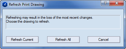
order of the pages is saved.The Refresh Print Drawing dialog box appears.