Generating clip path (bleed) on a single side
When you place artwork onto a packaging design, you need to define
the areas that are vital for the placement of artwork. Once defined,
these areas are then used for the generation of bleed.
Generating bleed on a single side
Generally, bleed is defined on a single side of a design. The procedure
that follows walks you through the steps you need to do to define
this bleed. You can also define bleed for both
sides of a design.
To generate bleed on a single side of a design
- On the , click Generate
Bleed by Levels of Importance
 .
.
A contextual edit bar appears above the graphical
area. See details about what each button
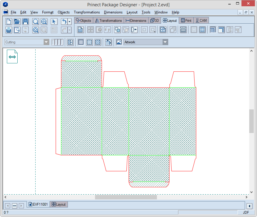
means and does. By default, you see the front side of the design.
By default, Prinect
marks the areas of importance set by default. You can set how Prinect marks the default
areas. See Step 5 later in this topic.
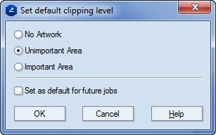
- Select the areas on which no artwork will be placed: click
No Artwork
 ,
and then, in the design, consecutively click the areas that will
be free of artwork.
,
and then, in the design, consecutively click the areas that will
be free of artwork.
- Select critical artwork areas: in the contextual edit bar click
Important Area
 ,
and then, in the design, consecutively click the respective areas.
,
and then, in the design, consecutively click the respective areas.
- Select less critical artwork areas: in the contextual edit
bar click Unimportant Area
 , and then,
in the design, consecutively click the respective areas.
, and then,
in the design, consecutively click the respective areas.
- (Optional) If you want to mark the entire design as the same
type of clipping area, click Set All Regions
 .
.
- After you have designated the important and unimportant areas,
click Generate Bleed
 .
.
The Bleed Generation
Options dialog box appears.
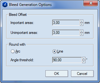
| Bleed Offset |
Enter values for the bleed distances for the important
and unimportant areas. NOTE: Normally, the value for the important
areas is greater than that for the unimportant areas, but
you can make them identical if that suits your case. |
| Important areas |
Offset for the important areas |
| Unimportant areas |
Offset for the unimportant areas |
| Round With |
Choose whether to use arcs or lines for the angle roundings
of the bleed: arcs or lines. |
| Angle threshold |
This field is available when you have chosen to use
lines for rounding the bleed contour. Type the value
for the angle at which you want the roundings to take effect. |
- To generate the bleed, click OK.
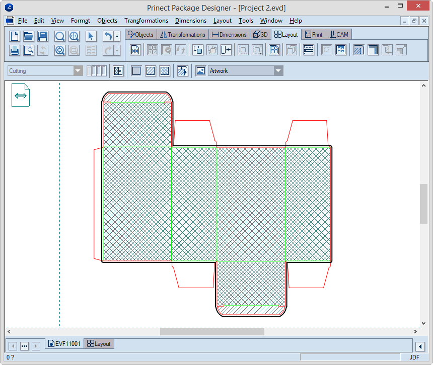
An example of generated bleed on a design.
In the Layers & Objects tabular view, notice the newly created
entry for the bleed object. It indicates that the created bleed is
applied to the front side.